Section 05 ENGINE (4-TEC)
Subsection 08 (ENGINE BLOCK)
BALANCER SHAFT SEAT DIAMETER mm (in)
NEW MINIMUM 31.984 (1.2592)
NEW MAXIMUM
32.000 (1.2598)
SERVICE LIMIT 31.960 (1.2583)
BALANCER SHAFT SEAT RADIAL
CLEARANCE mm (in)
SERVICE LIMIT 0.07 (.0028)
Installation
For installation, reverse the removal procedure.
Pay attention to following detail.
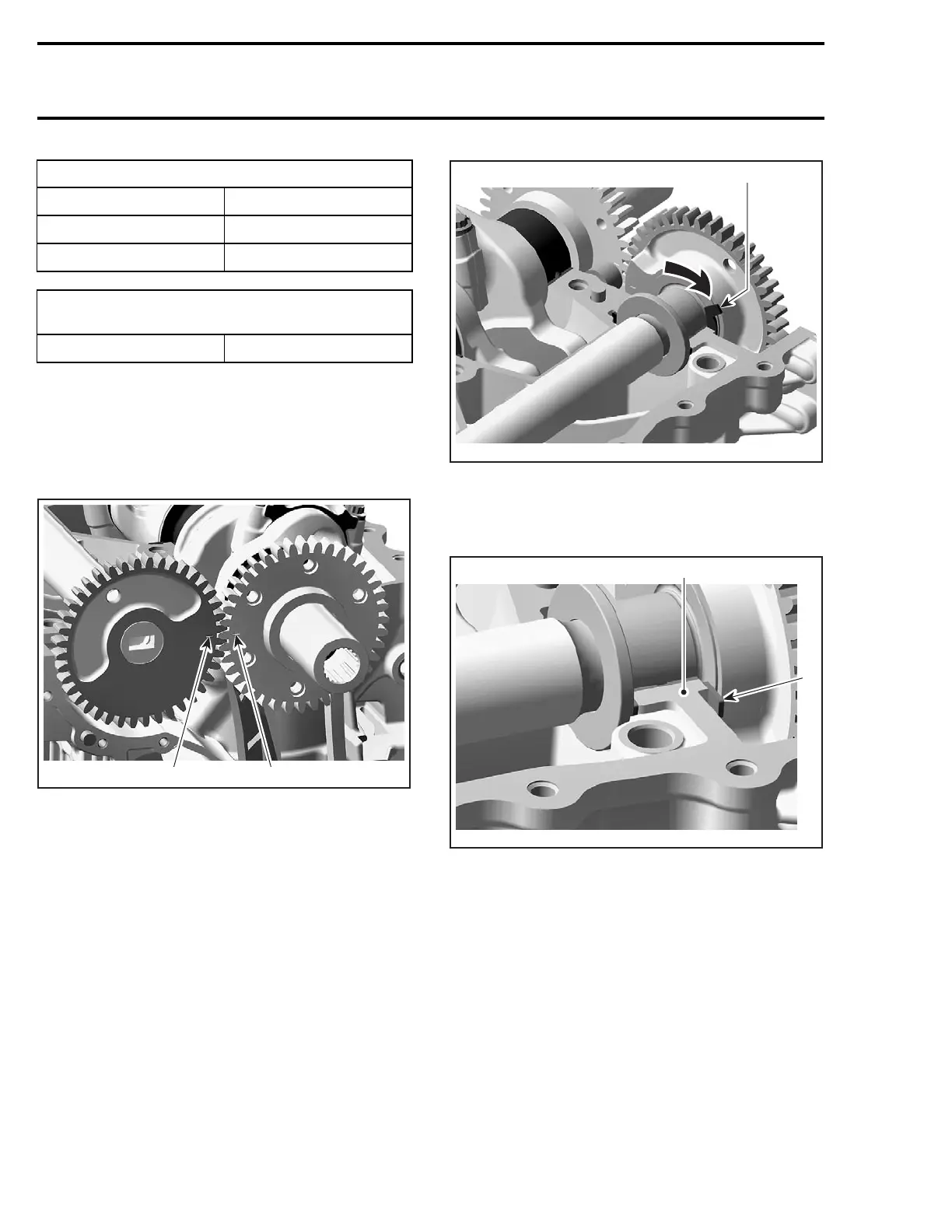
CAUTION: Balancer shaft and crankshaft marks
have to be aligned.
R1503motr17A
12
1. Mark on balancer shaft
2. Mark on crankshaft
CAUTION: Never forget thrust washers no. 6
on PTO side to control axial adjustment on bal-
ancer.
Insert thrust washers as soon as balancer shaft is
in place as per following illustration.
1
R1503motr20B
THRUST WASHER INSERT DIRECTION
1. Thrust washer
CAUTION: Thrust washers have to be flush
with the engine block sealing surface.
2
R1503motr22A
1
1. Thrust washer
2. Sealing surface
Install lower engine block half. Refer to ENGINE
BLOCK ASSEMBLY elsewhere in this section for
proper procedure to clean surfaces, apply Loctite
5910 and proper torquing sequence.
Install the crankshaft cover before mounting the
engine bracket. Apply oil on O-ring and press cov-
er in. Crankshaft cover has to be flush with engine
block surface.
282 smr2004-Complete Line Up

 Loading...


