Section 05 ENGINE (4-TEC)
Subsection 08 (ENGINE BLOCK)
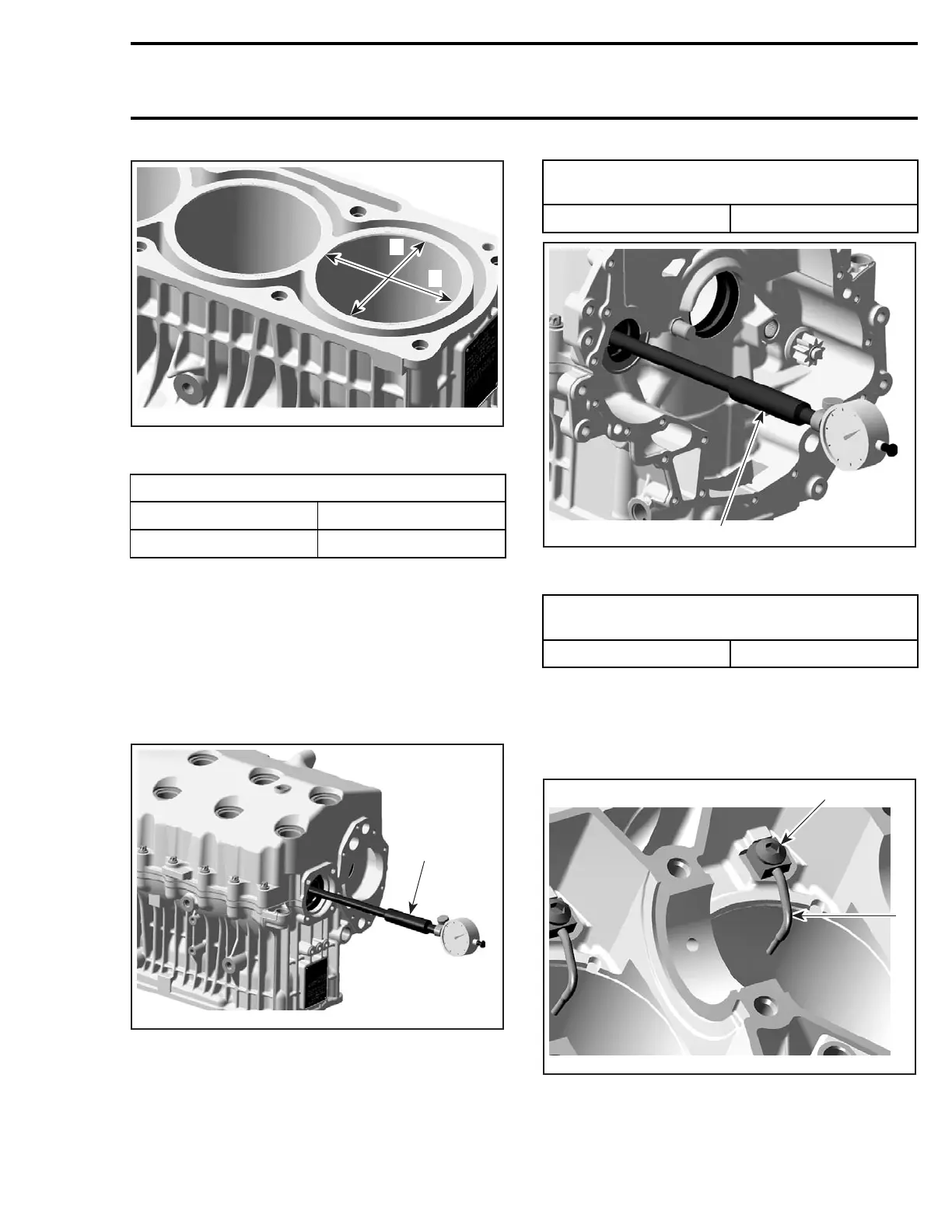
A
R1503motr25A
B
A. Perpendicular to crankshaft axis
B. Parallel to crankshaft axis
CYLINDER OUT OF ROUND mm (in)
NEW MAXIMUM
0.008 (.0003)
SERVICE LIMIT 0.015 (.0006)
Bushings
To measure the wear of the crankshaft bushings
no. 13 and no. 14 and balancer shaft bushings
no. 15, both engine block halves with OLD bush-
ings have to be screwed together as per tighten-
ing procedure described below.
Measure the inside diameter of the bushings with
a bore gauge.
1
R1503motr33A
ENGINE UPSIDE DOWN
1. Bore gauge
CRANKSHAFT BUSHING INSIDE
DIAMETER mm (in)
SERVICE LIMIT 50.1 (1.9724)
R1503motr34A
1
ENGINE UPSIDE DOWN
1. Bore gauge
BALANCER SHAFT BUSHING INSIDE
DIAMETER mm (in)
SERVICE LIMIT 32.11 mm (1.2642 in)
Replace bushings if they are out of specifications.
Oil Spray Nozzles
Remove oil spray nozzle no. 16 and banjo screw
no. 17 from engine block.
1
R1503motr38A
2
1. Banjo screw
2. Oil spray nozzle
smr2004-Complete Line Up 285

 Loading...


