Section 07 ENGINE MANAGEMENT (DI)
Subsection 02 (COMPONENT INSPECTION AND ADJUSTMENT)
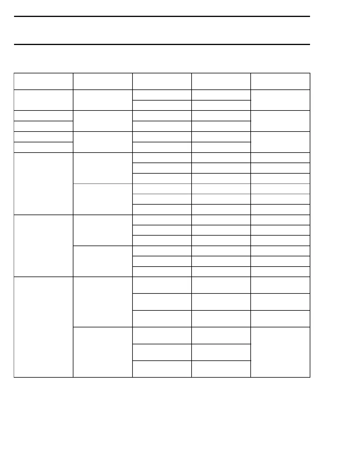
Electrical Tests
COMPONENT CONNECTOR
TERMINAL
NUMBER
WIRE COLOR VALUE
26 and terminal B PU/PK
Fuel pump AMP no. 4
24 and terminal D BK/PK
0 ohm (continuity)
Fuel injector MAG 7and13 BL/PU and BL/BK
Fuel injector PTO
AMP no. 4
8and14 GN/PU and GN/BK
1.7 - 1.9 ohms
Direct injector MAG 5and15 BL/BW and BL/PK
Direct injector PTO
AMP no. 4
6and21 GN/BW and GN/PK
1-1.6ohms
1 and engine ground PU/BW 5V
2 and engine ground BK/BW 0-0.5V
TPS
3 and engine ground PU/BW 4.75 - 5 V
10 and 14 PU/BW and BK/BW 1600 - 2400 ohms
5and14 WH/BW and BK/BW 2500 ohms at idle
Throttle position
sensor MAG (TPS)
AMP no. 3
5and10 WH/BW and PU/BW 1200 ohms at idle
1 and engine ground PU/RD 5V
2 and engine ground BK/RD 0-0.5V
TPS
3 and engine ground WH/RD 0V
3and18 BK/RD and PU/RD 1600 - 2400 ohms
1and3 WH/RD and BK/RD 1000 ohms at idle
Throttle position
sensor PTO (TPS)
AMP no. 4
1and18 WH/RD and BK/RD 2500 ohms at idle
Terminal 4 and
ground
BK
0 V (with a small
mV tolerance)
Terminal 5 and
ground
GY/RD 12 V
CPS
(Deutsche
connector)
Terminal 6 and
ground
GY/YL
5V
Terminal 7 and
terminal 6 of CPS
GY/YL
Terminal 6 and
terminal 5 of CPS
GY/RD
Crankshaft position
sensor (CPS)
AMP no. 2
Terminal 14 and
terminal 4 of CPS
BK
0 ohm (continuity)
374 smr2004-Complete Line Up

 Loading...


