Section13PROPULSION
Subsection 02 (DRIVE SYSTEM)
Install the large washer no. 28 and nuts no. 21.
Slightly tighten nuts but keep loose so that the as-
sembly still can move and self adjust when insert-
ing the alignment shaft further in this procedure.
NOTE: Completely tightening nuts would make
the alignment more difficult.
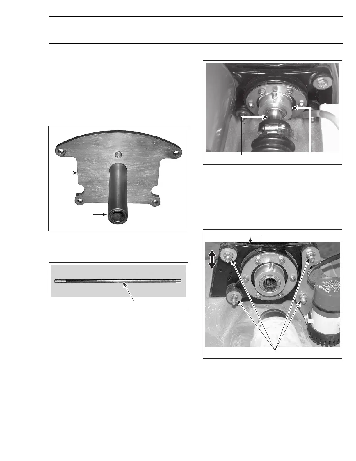
Align the seal carrier using the following tools:
– support plate kit (P/N 529 035 570)
F19J09A
1
2
1. Plate (P/N 529 035 507)
2. Support (P/N 529 035 511)
– alignment shaft (P/N 295 000 141).
F00B0GA
1
1. Alignment shaft
Install support plate at rear of watercraft.
Carefully slide shaft through seal carrier and shaft
support. Ensure that shaft goes farther than shaft
support.
F05I08A
1 2
TYPICAL
1. Alignment tool
2. Seal carrier
If alignment tool does not slide easily through seal
carrier, perform the alignment as follows.
For vertical alignment, loosen damping support
nuts no. 30 andmovethesupportno. 29 up and
down as necessary.
F00B25A
2
1
1. Damping support
2. Loosen nuts
When done, ensure to apply Loctite 243 on screw
threadsthentorquescrewsto22N•m(16lbf•ft)
in a criss-cross sequence.
For horizontal alignment, loosen shaft support
screws no. 32 and move the support no. 31
sideways as necessary.
smr2004-Complete Line Up 667

 Loading...


