Section 14 STEERING SYSTEM
Subsection 01 (STEERING SYSTEM)
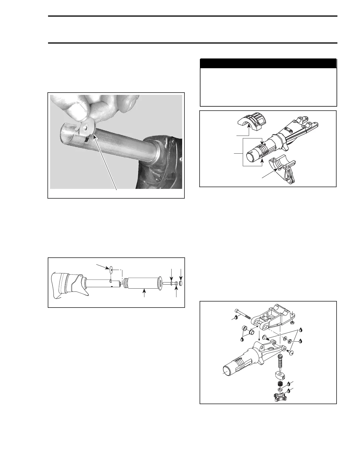
Handle Grip and Grip Insert
When installing the grip insert no. 21 in the han-
dlebar no. 22, ensure that it is properly inserted in
the slot at the end of the handlebar tubing.
F02K0JA
1
1. Grip insert
Install grip no. 1 on handlebar no. 22 matching it
to the notch in the handlebar.
Install flat washer no. 23 and screw no. 3.
Torque screw to 7 N•m(62lbf•in).
Install cap no. 2.
F02K0KA
1
2
4
53
1. Grip insert
2. Grip
3. Flat washer
4. Screw. Torque to 7 N•m(62lbf•
in)
5. Cap
CAUTION: Ensure to install flat washer other-
wise screw will damage grip end.
Steering Stem Arm and Support
Position steering stem arm no. 15 and support
no. 16 onto steering stem.
WARNING
Make sure the integrated flat keys of the steer-
ing stem arm and support are properly seat-
ed in steering stem keyways. Steering stem
arm must be locked in place before torquing
the bolts.
F07K09A
2
1
2
1. Keyways
2. Integrated flat key
Replace lock nuts no. 18 by new ones.
Torque bolts no. 17 of steering stem arm to 6 N•m
(53 lbf•in).
Steering Stem and Steering Support
GTX 4-TEC Supercharged Limited Models Only
Install support bushings no. 50 on steering sup-
port.
Apply Loctite 767 antiseize lubricant (P/N 413 701
000) on pivot bolt no. 47.
CAUTION: Make sure antiseize lubricant does
not come in contact with threads of bolt.
F07K0PB
1
2
3
3
2
1
1. Antiseize lubricant
2. Loctite 271
3. Loctite 243
smr2004-Complete Line Up 693

 Loading...


