Section 14 STEERING SYSTEM
Subsection 01 (STEERING SYSTEM)
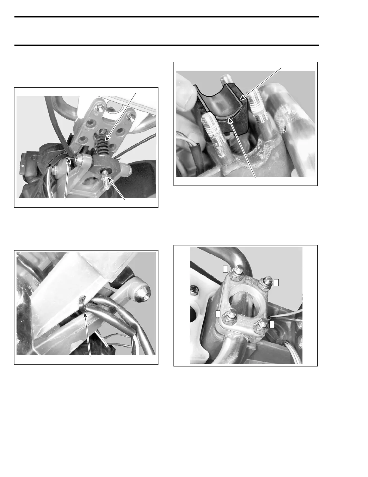
Install steering support no. 48 to steering stem
no. 49 and secure with pivot bolt no. 47.Install
nut and torque to 26 N•m(19lbf•ft).
F07K0RA
1
32
1. Adjuster screw
2. Apply Loctite 243
3. Locking tie
Ensure wire harness is properly secured to steer-
ing support with a locking tie.
F07K0WA
1
1. Locking tie holding harness to steering support
Handlebar
GTX 4-TEC Supercharged Limited Models Only
Before installing handlebar
, position stopper
no. 33 and rubber pad no. 32.
CAUTION: Rubber pad must not exceed stop-
per.
F07K0UA
1
1
1. Pad must not exceed stopper
All Models
Position handlebar no. 22. Install steering clamp
no. 44 and secure with new elastic stop nuts M8.
Torque nuts to 26 N•m(19lbf•ft) as per the fol-
lowing sequence.
F07K0VA
1
3
2
4
TORQUE SEQUENCE
Ball Joint
Secure the steering cable ball joint no. 19 to the
nozzle as per following illustrations.
CAUTION: Ensure the ball joint is parallel
(± 10°) to the nozzle arm.
694 smr2004-Complete Line Up

 Loading...


