Section 18 WIRING DIAGRAM
Subsection 01 (WIRING DIAGRAMS)
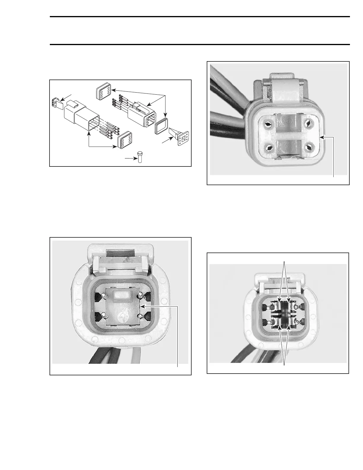
Connector Disassembly
All Models
F00H1CA
1
3
4
2
3
1. Male connector
2. Female connector
3. Secondary lock
4. Sealing cap
CAUTION: Do not apply dielectric grease on
terminal inside connector.
To remove terminals from connector, proceed as
follows:
– Using a long nose pliers, pull out the lock.
1
V01G0OA
FEMALE CONNECTOR
1. Female lock
V01G0PA
1
MALE CONNECTOR
1. Male lock
NOTE: Before extraction, push wire forward to
relieve pressure on retaining tab.
– Insert a 4.8 mm (.189 in) wide screwdriver blade
inside the front of the terminal cavity.
– Pry back the retaining tab while gently pulling
wire back until terminal is removed.
V01G0QA
1
1
FEMALE CONNECTOR
1. Retaining tab
To install:
– For insertion of a terminal, make sure the lock
is removed.
– Insert terminal into appropriate cavity and push
asfarasitwillgo.
smr2004-Complete Line Up 789

 Loading...


