Technical specifications
A.10 Analog signal modules (SMs)
S7-1200 Programmable controller
System Manual, V4.2, 09/2016, A5E02486680-AK
1469
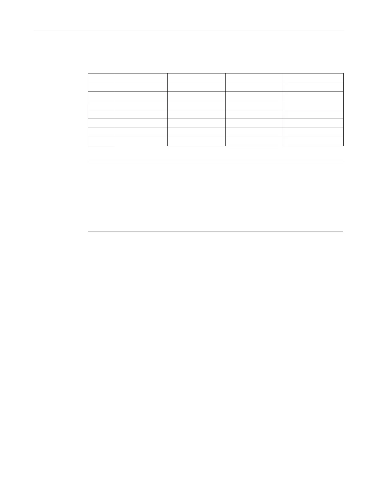
Table A- 156 Connector pin locations for SM 1234 AI 4 x 13 Bit / AQ 2 x 14 bit (6ES7234-4HE32-
0XB0)
2 M / 24 V DC No connection No connection No connection
Note
Unused voltage input channels should be shorted.
Unused current input channels should be set to the 0 to 20 mA range and/or disable broken
wire error reporting.
configured for current mode will not conduct loop current unless the module is
Current input channels will not operate unless external power is supplied to the transmitter.

 Loading...


