EasyManua.ls Logo

Siemens SIMATIC S7-1200 - Page 1475

Siemens SIMATIC S7-1200
1614 pages
To Next Page IconTo Next Page
To Previous Page IconTo Previous Page
Loading...
Technical specifications
A.11 Thermocouple and RTD signal modules (SMs)
S7-1200 Programmable controller
System Manual, V4.2, 09/2016, A5E02486680-AK
1475
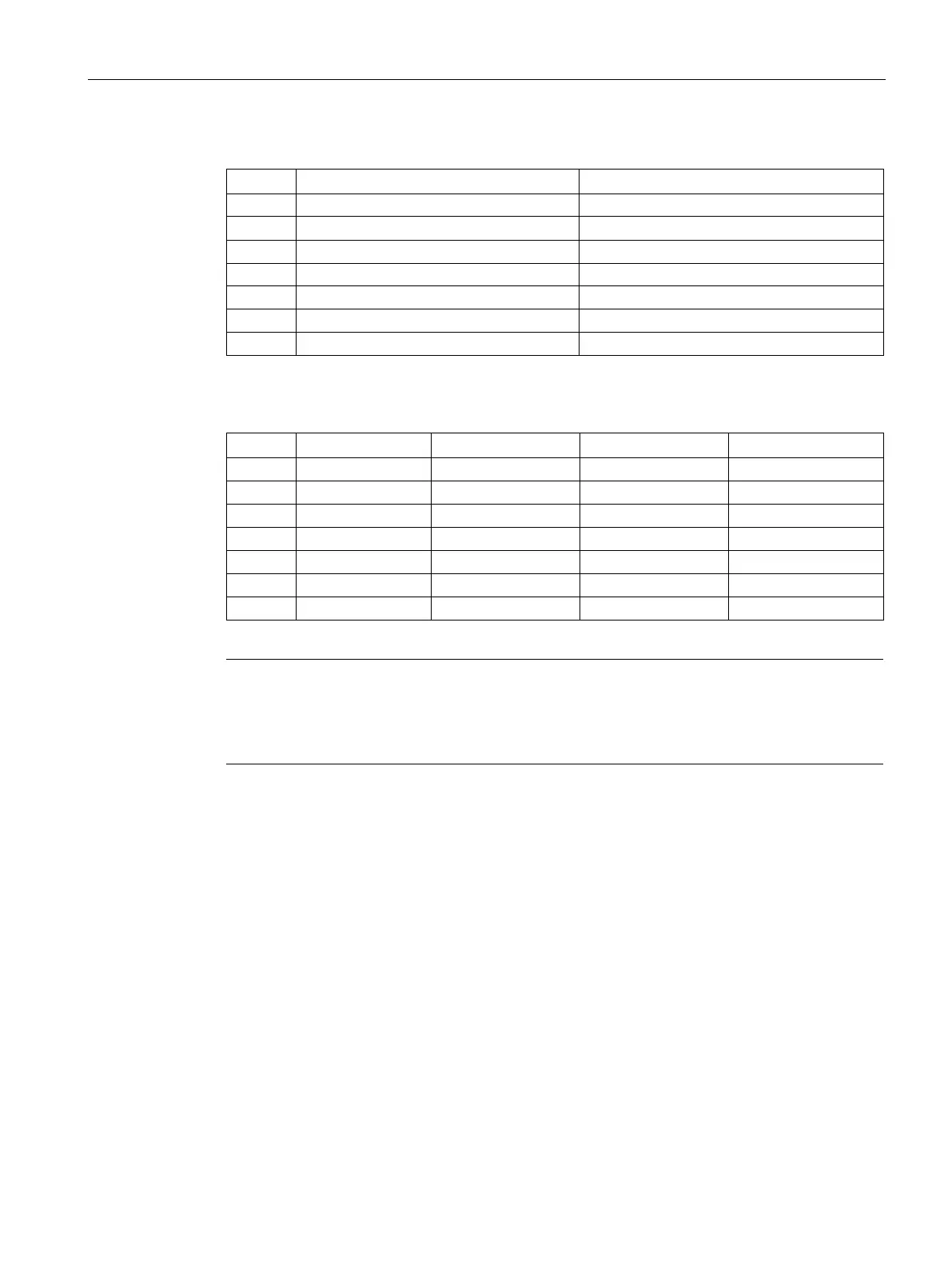
Table A- 167 Connector pin locations for SM 1231 AI 4 x TC 16 bit (6ES7231-5QD32-0XB0)
Pin
X10 (gold)
X11 (gold)
1
L+ / 24 V DC
No connection
2 M / 24 V DC No connection
3
Functional Earth
No connection
4 AI 0+ /TC AI 2+ /TC
5
AI 0- /TC
AI 2- /TC
6
AI 1+ /TC
AI 3+ /TC
7
AI 1- /TC
AI 3- /TC
Table A- 168 Connector Pin Locations for SM 1231 AI 8 x TC bit (6ES7231-5QF32-0XB0)
Pin
X10 (gold)
X11 (gold)
X12 (gold)
X13 (gold)
1
L+ / 24 V DC
No connection
No connection
No connection
2
M / 24 V DC
No connection
No connection
No connection
3
Functional Earth
No connection
No connection
No connection
4
AI 0+ /TC
AI 2+ /TC
AI 4 I- /TC
AI 6 I- /TC
5
AI 0- /TC
AI 2- /TC
AI 4 I+ /TC
AI 6 I+ /TC
6
AI 1+ /TC
AI 3+ /TC
AI 5 M- /TC
AI 7 M- /TC
7
AI 1- /TC
AI 3- /TC
AI 5 M+ /TC
AI 7 M+ /TC
Note
Unused analog inputs should be shorted.
The thermocouple unused channels can be deactivat
ed. No error will occur if an unused
channel is deactivated.

Table of Contents

Other manuals for Siemens SIMATIC S7-1200

Related product manuals