Technical specifications
A.13 Digital signal boards (SBs)
S7-1200 Programmable controller
1506 System Manual, V4.2, 09/2016, A5E02486680-AK
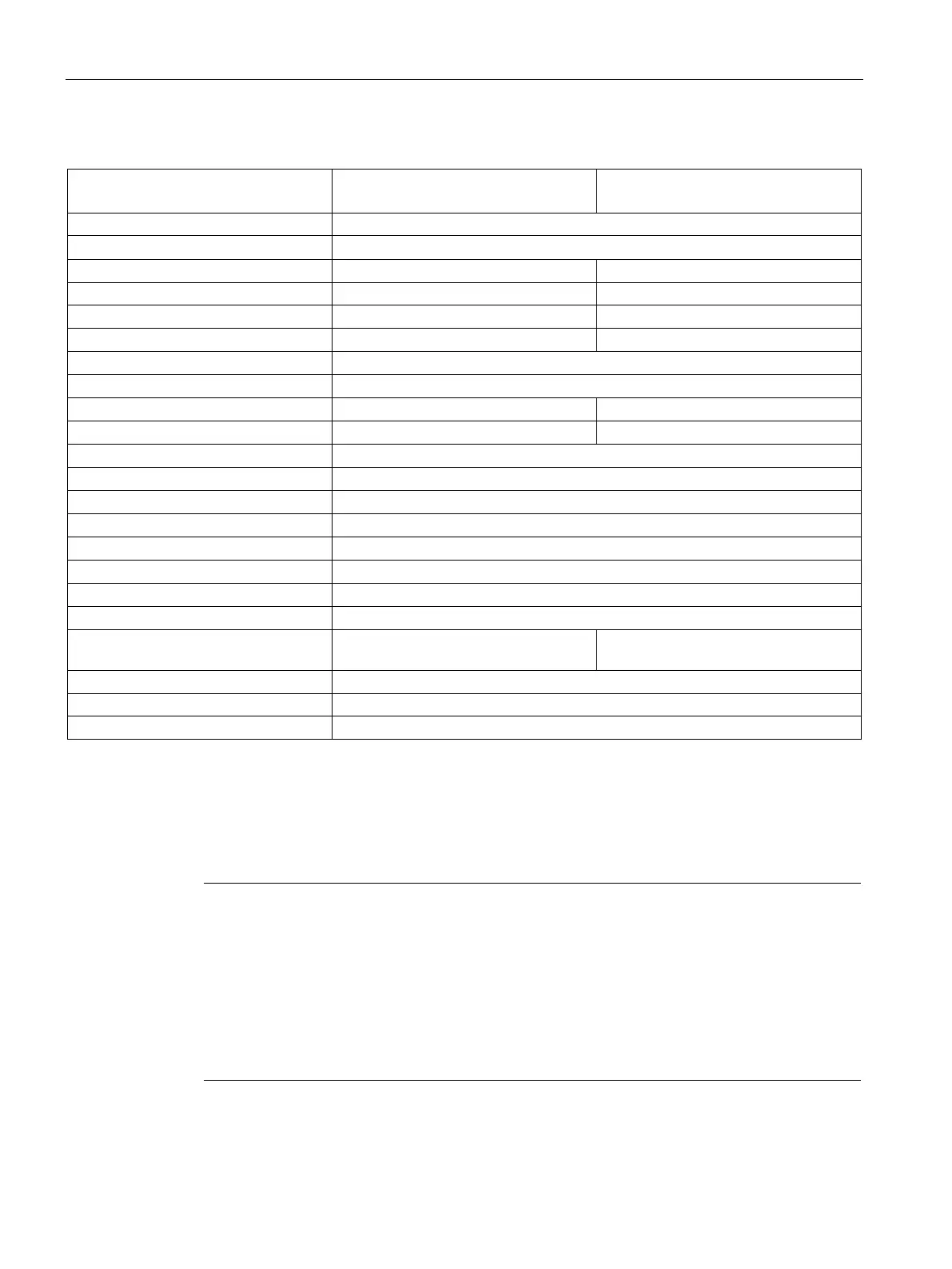
Table A- 197 Digital outputs
SB 1223 DI 2 x 24 V DC /
DQ 2 x 24 V DC, 200 kHz
SB 1223 DI 2 x 5 V DC /
DQ 2 x 5 V DC, 200 kHz
Output type Solid state - MOSFET sink and source
1
Logic 1 signal at max. current
Logic 0 signal at max. current
On state contact resistance
Leakage current per point
Isolation (field side to logic)
1 (no isolation to inputs)
Switching delay 1.5 μs + 300 ns rise
200 ns + 300 ns rise
Last value or substitute (default value 0)
Number of outputs on simultaneously
Because both sinking and sourcing configurations are supported by the same circuitry, the active state of a sourcing
load is opposite that of a sinking load. A source output exhibits positive logic (Q bit and LED are ON when the load has
current flow), while a sink output exhibits negative logic (Q bit and LED are OFF when the load has current flow). If the
module is plugged in with no user program, the default for this module is 0 V, which means that a sinking load will be
Note
When switching frequencies above 20
kHz, it is important that the digital inputs receive a
square wave. Consider the following options to improve the signal quality to the inputs
:
Minimize the cable length
Change a driver from a sink only driver to a sinking and sourcing driver
Change to a higher quality cable
Reduce the circuit/components from 24 V to 5 V
Add an external load at the input

 Loading...


