Technical specifications
A.13 Digital signal boards (SBs)
S7-1200 Programmable controller
System Manual, V4.2, 09/2016, A5E02486680-AK
1507
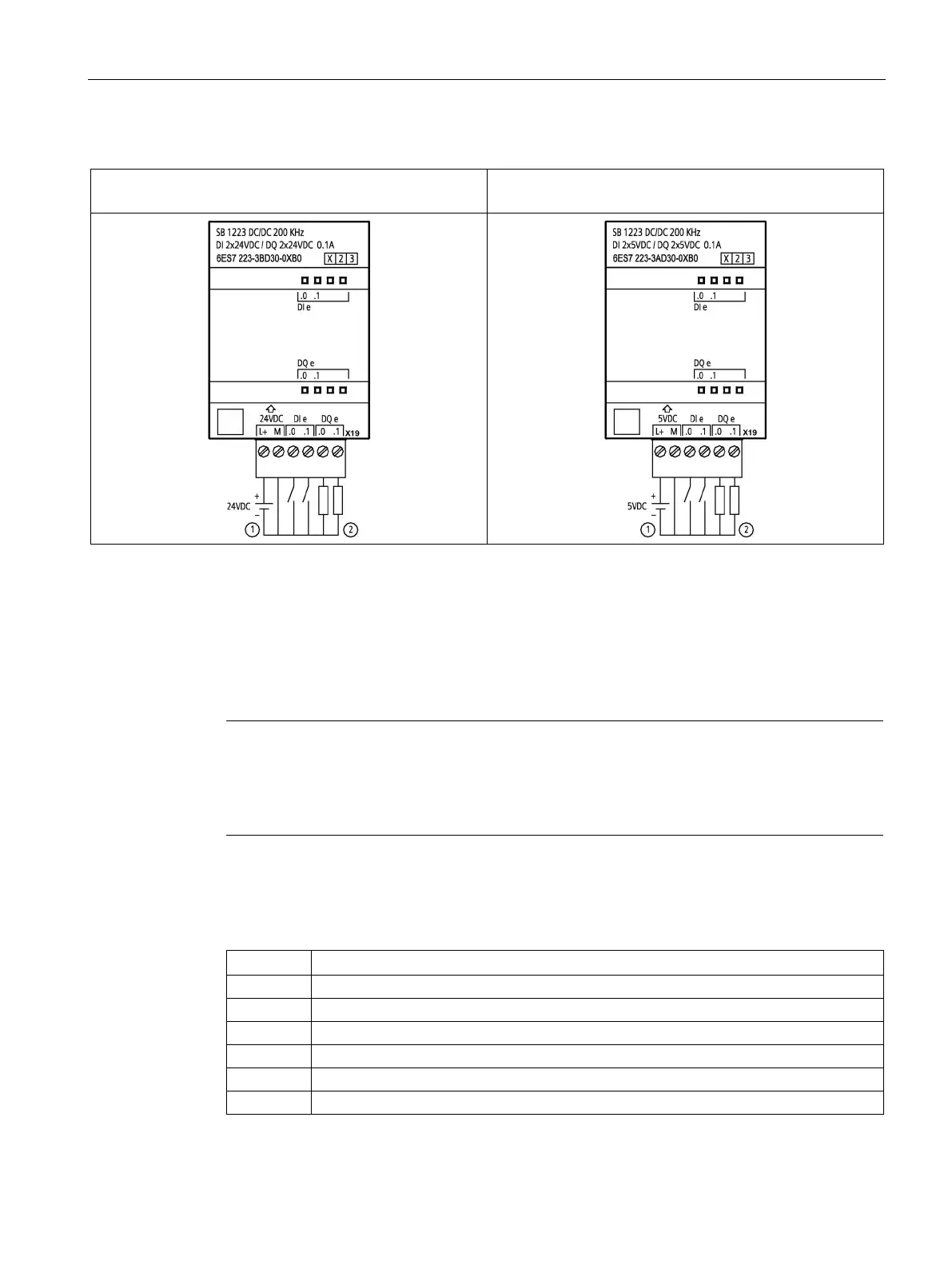
Table A- 198 Wiring diagrams for the 200 kHz digital input/output SBs
SB 1223 DI 2 x 24 V DC/DQ 2 x 24 V DC,
200 kHz (6ES7223-3BD30-0XB0)
SB 1223 DI 2 x 5 V DC / DQ 2 x 5 V DC,
200 kHz (6ES7223-3AD30-0XB0)
Supports sourcing inputs only
For sourcing outputs, connect "Load" to "-" (shown). For sinking outputs, connect "Load" to "+".
1
Because both sinking
and sourcing configurations are supported by the same circuitry, the active state of a sourcing load is opposite that of a
sinking load. A source output exhibits positive logic (Q bit and LED are ON when the load has current flow), while a sink
output exhibits negative logic (Q bit and LED are OFF when the load has current flow). If the module is plugged in with
no user program, the default for this module is 0 V, which means that a sinking load will be turned ON.
Note
Ensure that the M connection wire is securely grounded. Loss of the ground wire connection
to the high
-speed DQ SBs may allow enough leakage current to activate a DC load. If the
outputs are used for critical DC load applications, extra caution should be exercised by using
a redundant ground wire to the SB.
Table A- 199 Connector pin locations for SB 1223 DI 2 x 24 V DC/DQ 2 x 24 V DC, 200 kHz
(6ES7223-3BD30-0XB0)

 Loading...


