Installation
4.3 Installation and removal procedures
S7-1200 Programmable controller
58 System Manual, V4.2, 09/2016, A5E02486680-AK
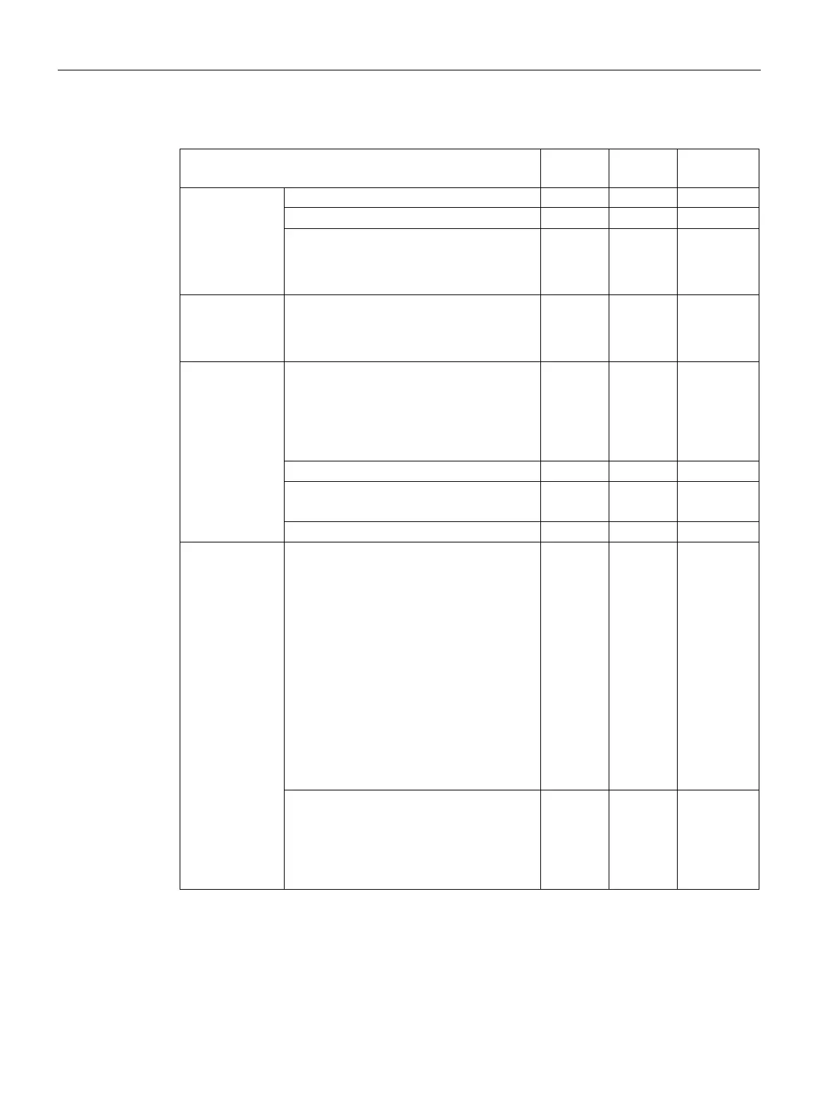
Table 4- 1 Mounting dimensions (mm)
CPU
CPU 1214C 110 55 --
CPU 1215C 130 65 (top) Bottom:
C1: 32.5
C2: 65
CPU 1217C 150 75 Bottom:
C1: 37.5
C2: 75
Signal modules Digital 8 and 16 point
Analog 2, 4, and 8 point
Thermocouple 4 and 8 point
RTD 4 point
45 22.5 --
Digital DQ 8 x Relay (Changeover)
Analog 16 point
70 35 --
SM 1238 Energy Meter module
Communication
interfaces
CM 1241 RS232, and
CM 1241 RS422/485
CM 1243-5 PROFIBUS master and
CM 1242-5 PROFIBUS slave
CM 1242-2 AS-i Master
CP 1242-7 GPRS V2
CP 1243-7 LTE-EU
CP 1243-1 DNP3
CP 1243-1 IEC
CP 1243-1
CP1243-1 PCC
CP 1243-8 IRC
30 15 --
TS (TeleService) Adapter IE Advanced
1
TS (Teleservice) Adapter IE Basic
1
TS Adapter
TS Module
30
30
15
15
--
--
Before installing the TS (TeleService) Adapter IE Advanced or IE Basic, you must first connect the
TS Adapter and a TS module. The total width ("width A") is 60 mm.

 Loading...


