Installation
4.3 Installation and removal procedures
S7-1200 Programmable controller
System Manual, V4.2, 09/2016, A5E02486680-AK
59
Each CPU, SM, CM, and CP supports mounting on either a DIN rail or on a panel. Use the
DIN rail clips on the module to secure the device on the rail. These clips also snap into an
extended position to provide screw mounting positions to mount the unit directly on a panel.
The interior dimension of the hole for the DIN clips on the device is 4.3 mm.
A 25 mm thermal zone must be provided above and below the unit for free air circulation.
Installing and removing the S7-1200 devices
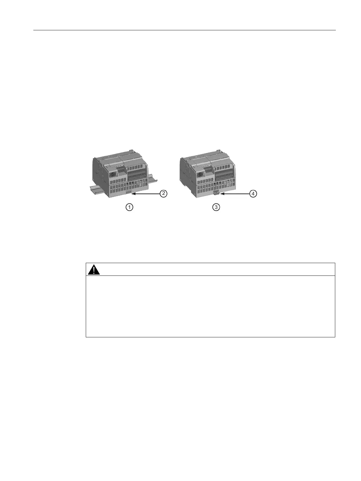
The CPU can be easily installed on a standard DIN rail or on a panel. DIN rail clips are
provided to secure the device on the DIN rail. The clips also snap into an extended position
to provide a screw mounting position for panel-mounting the unit.
DIN rail clip in latched position
Clip in extended position for panel mounting
Before you install or remove any electrical device, ensure that the power to that equipment
has been turned off. Also, ensure that the power to any related equipment has been turned
off.
Installation or removal of S7-1200 or related equipment with the power applied could cause
electric shock or unexpected operation of equipment.
Failure to disable all power to the S7-1200 and related equipment during installation or
removal procedures could result in death, severe personal injury and/or property damage
due to electric shock or unexpected equipment operation.
Always follow appropriate safety precautions and ensure that power to the S7-1200 is
disabled before attempting to install or remove S7-1200 CPUs or related equipment.

 Loading...


