111 Programmable Hardware Manual (PHM)
© Tibbo Technology Inc.
·
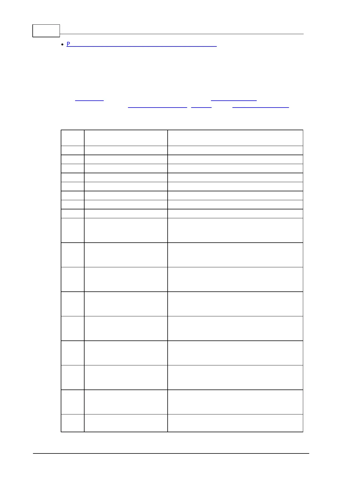
Power, Reset, PLL Control, and Mode Selection Lines
I/O pin assignment
Notes (refer to
superscript numbers
placed after pin #):
1. This line is 5V-tolerant and can be interfaced to 5V CMOS devices directly.
2. This line can be mapped to serve as an RTS, W0 output, or CLOCK output line of
a serial port. The line can also be assigned to an I2C/SPI channel, or act as an
interface line of the Wi-Fi add-on module, keypad, or an LED control channel.
3. This line can serve as a CTS, W0&1 input, or CLOCK input line of a serial port.
General-purpose I/O line 0 (P0.0).
General-purpose I/O line 1 (P0.1).
General-purpose I/O line 2 (P0.2).
General-purpose I/O line 3 (P0.3).
General-purpose I/O line 4 (P0.4).
General-purpose I/O line 5 (P0.5).
General-purpose I/O line 6 (P0.6).
General-purpose I/O line 7 (P0.7).
General-purpose I/O line 8 (P1.0);
RX, W1 input, and DATA input of the serial
port 0.
General-purpose I/O line 9 (P1.1);
TX, W1 output, and DATA output of the
serial port 0.
General-purpose I/O line 10 (P1.2);
RX, W1 input, and DATA input of the serial
port 1.
General-purpose I/O line 11 (P1.3);
TX, W1 output, and DATA output of the
serial port 1.
General-purpose I/O line 12 (P1.4);
RX, W1 input, and DATA input of the serial
port 2.
General-purpose I/O line 13 (P1.5);
TX, W1 output, and DATA output of the
serial port 2.
General-purpose I/O line 14 (P1.6);
RX, W1 input, and DATA input of the serial
port 3.
General-purpose I/O line 15 (P1.7);
TX, W1 output, and DATA output of the
serial port 3.
General-purpose I/O line 16 (P2.0);
interrupt line 0.
 Loading...