331 Programmable Hardware Manual (PHM)
© Tibbo Technology Inc.
Register address, high
byte
Register address, low
byte
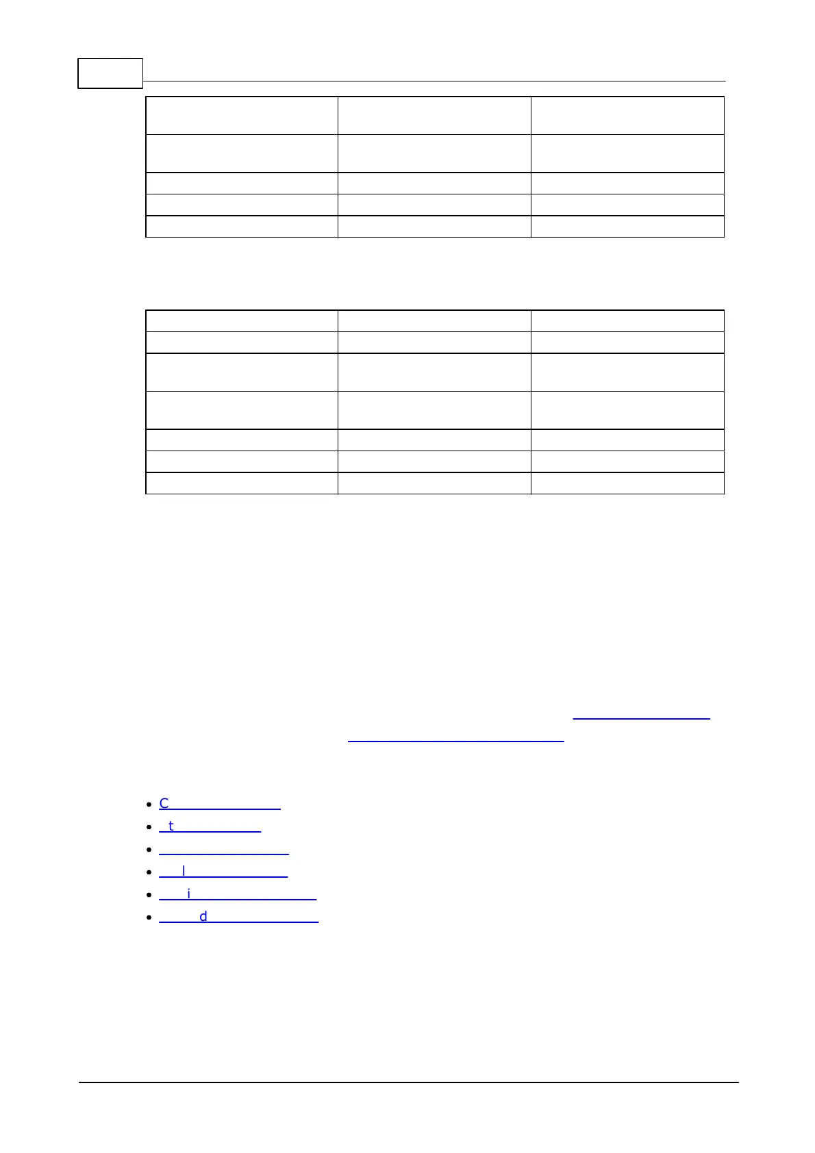
SPI read transaction
Register address, high
byte
Register address, low
byte
Address auto-increments
Register address sent in bytes 2 and 3 of every SPI transaction will auto-increment
with each data byte send to or received from the FPGA.
This allows you to write or read multiple registers within the span of a single
transaction.
Registers
Registers described here are implemented within the IR_Remote_bitmap.bin FPGA
project, which needs to be uploaded into the FPGA during the initialization process.
Registers are accessed using SPI read and write transactions.
Available registers:
·
Command register
·
Status register
·
TX length registers
·
RX length registers
·
Carrier divider registers
·
TX and RX data buffers
 Loading...