EasyManuals Logo

Tibbo EM1000 User Manual

Tibbo EM1000
570 pages
To Next Page IconTo Next Page
To Previous Page IconTo Previous Page
Page #228 background imageLoading...
Page #228 background image
217 Programmable Hardware Manual (PHM)
© Tibbo Technology Inc.
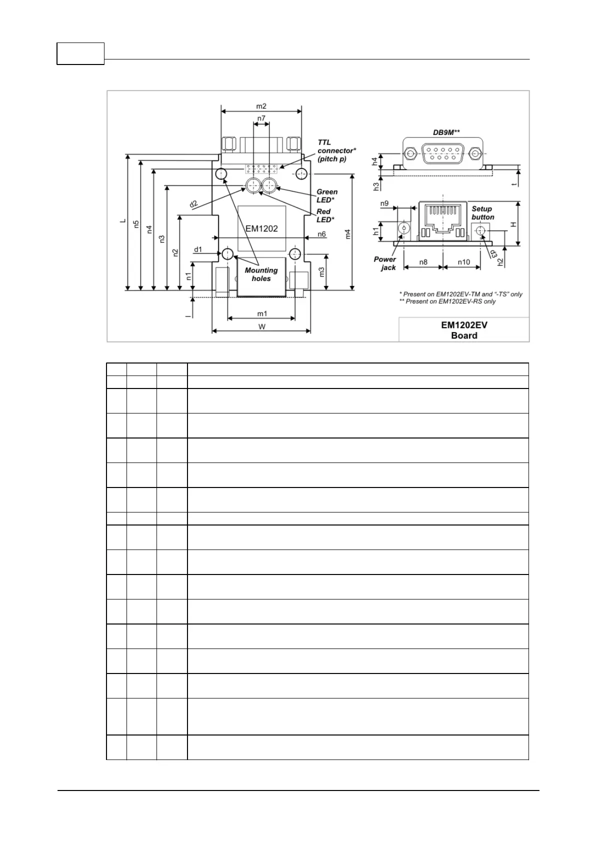
Mechanical Dimensions
L
Max.
52.6
Board length
W
Max.
38.0
Board width
l
Aver
.
2.6
Distance from the front edge of the PCB to the front surface of
the RJ45 jack, power jack, setup button
H
Max.
17.2
Board height with components installed on the top side of the
board
t
Aver
.
1.6
PCB thickness
d1
Aver
.
3.6
Mounting hole diameter
d2
Aver
.
5.0
LED diameter (these LEDs are present on the EM1202EV-RS only)
d3
Max.
3.5
Setup button diameter
m
1
Aver
.
26.0
Horizontal distance between the mounting holes (first pair)
m
2
Aver
.
31.0
Horizontal distance between the mounting holes (second pair)
m
3
Aver
.
14.0
Distance from the front edge of the PCB to the first pair mounting
holes
m
4
Aver
.
45.0
Distance from the front edge of the PCB to the second pair of
mounting holes
n1
Aver
.
11.0
PCB outline dimension
n2
Aver
.
29.0
PCB outline dimension
n3
Aver
.
40.5
Distance from the front edge of the PCB to the LEDs (present on
the EM1202EV-RS only)
n4
Aver
.
47.0
Distance from the front edge of the PCB to the horizontal
centerline of the TTL interface connector (present on the
EM1202EV-TM and "-TS" only)
n5
Aver
.
50.1
PCB outline dimension

Table of Contents

Questions and Answers:

Question and Answer IconNeed help?

Do you have a question about the Tibbo EM1000 and is the answer not in the manual?

Tibbo EM1000 Specifications

General IconGeneral
BrandTibbo
ModelEM1000
CategoryControl Unit
LanguageEnglish