242Development Systems
© Tibbo Technology Inc.
Use the following code to turn on the backlight:
io.num=PL_IO_NUM_47
io.enabled=YES
io.state=LOW
TEV-IBx Boards
The TEV-IBx are interface boards. Two boards are currently supplied by Tibbo:
·
TEV-IB0: RS232/422/485 serial port board (each EM1000-TEV system has two of
them);
·
TEV-IB1: 3 x opto-input/ 3 x relay output board (each EM1000-TEV system has
two of them). Opto-inputs can optionally be used to connected a Wiegand or
clock/data reader.
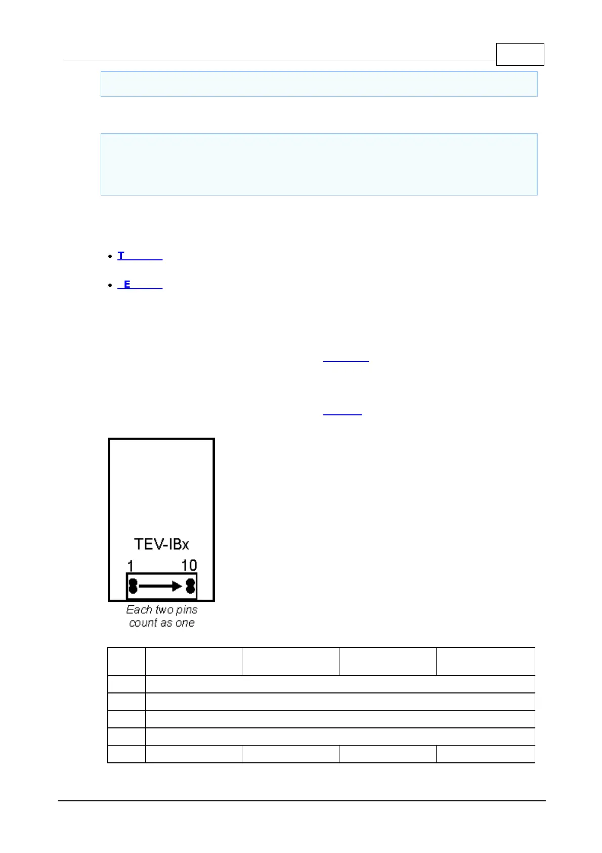
TEV-IBx Board Connector
The TEV-IBx boards are connected to the TEV-MB0 motherboard through a 2x10-pin
connector. Each two pins of the connector are combined together for better
electrical contact. Therefore, the connector effectively has 10 lines.
Each EM1000-TEV system has four interface boards and each board is controlled
through one of the four serial ports of the EM1000 module.

 Loading...