71 Programmable Hardware Manual (PHM)
© Tibbo Technology Inc.
4.4.1.5
Power, Reset, and Mode Selection Lines
The EM510 should be powered from a stabilized DC power supply with a nominal
output voltage of 3.3V (+/- 5% tolerance). The module's current consumption is
approximately 110mA. Providing an adequate power supply is very important — a
poorly built circuit may affect the EM510's operation. We recommend that you use a
switching power regulator. One example of such a circuit is shown below.
External reset is optional — the EM510 generates a reliable power-on/brown-out
reset on its own. If the EM510 is to serve as a communications co-processor in a
larger system that has its own CPU (microcontroller) it is also OK to control the RST
line through a general-purpose I/O pin of this CPU. Reset pulses for the EM510 can
then be generated programmatically, by setting the I/O pin of the CPU to LOW and
then to HIGH.
The function of the MD line is described in Setup Button (MD line).
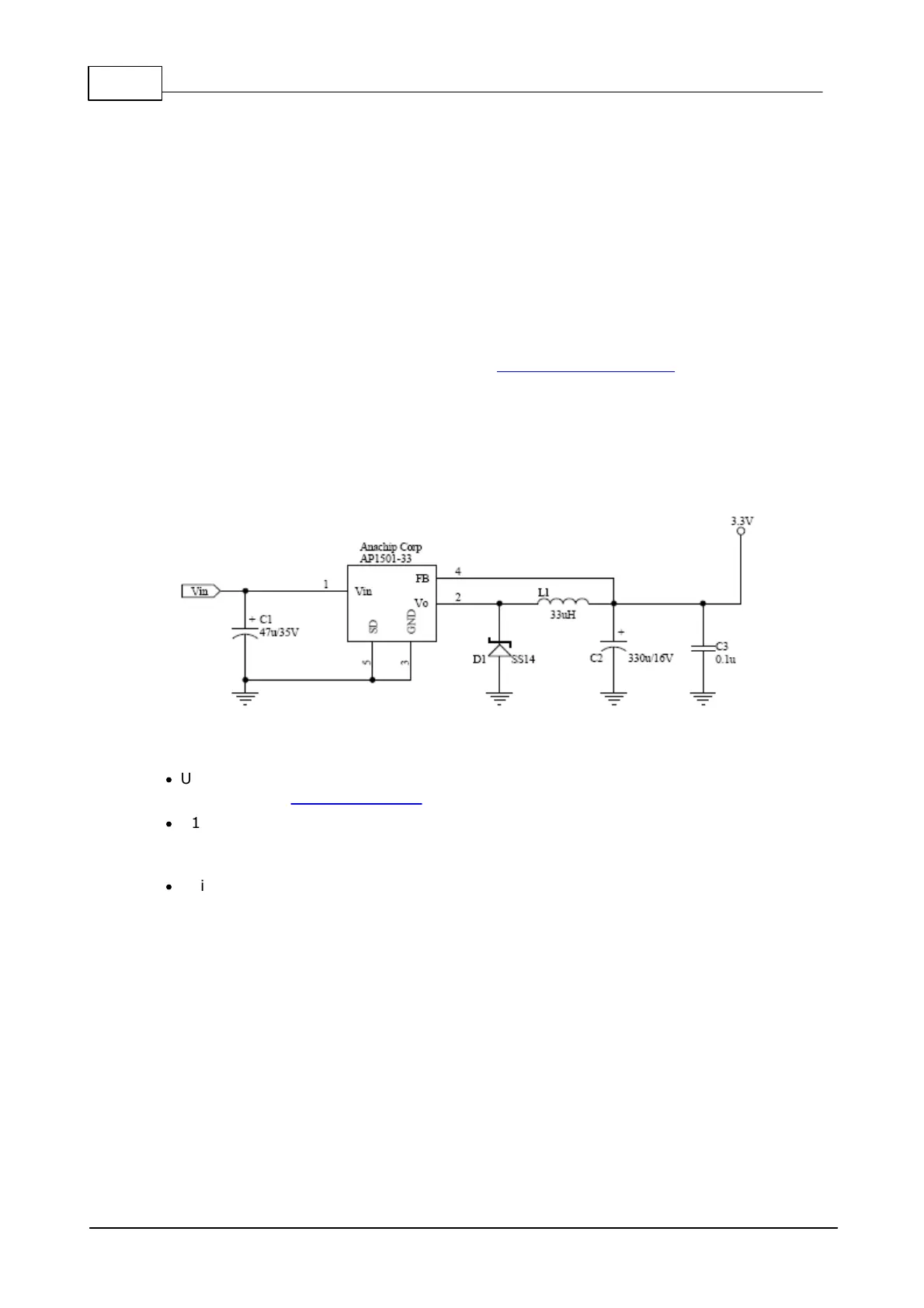
Power supply circuit
Many power supply circuits will work well. The one below is being used by Tibbo.
This circuit can handle input voltages in the 9-24V range.
Notes:
·
U1 (AP1501-33) is a popular power IC manufactured by Anachip (now Diodes
Incorporated, www.diodes.com)
·
C1 and C2 capacitors: Do not use SMD capacitors -- use regular through-hole
aluminum capacitors. This really helps reduce the noise produced by the power
supply.
·
This is an analog circuit, so layout matters. Apply reasonable "good layout" effort.

 Loading...