EasyManuals Logo

Tibbo EM1000 User Manual

Tibbo EM1000
570 pages
To Next Page IconTo Next Page
To Previous Page IconTo Previous Page
Page #518 background imageLoading...
Page #518 background image
507 Programmable Hardware Manual (PHM)
© Tibbo Technology Inc.
(4)
"Connection" means a BLE link or a Wi-Fi association with an access point.
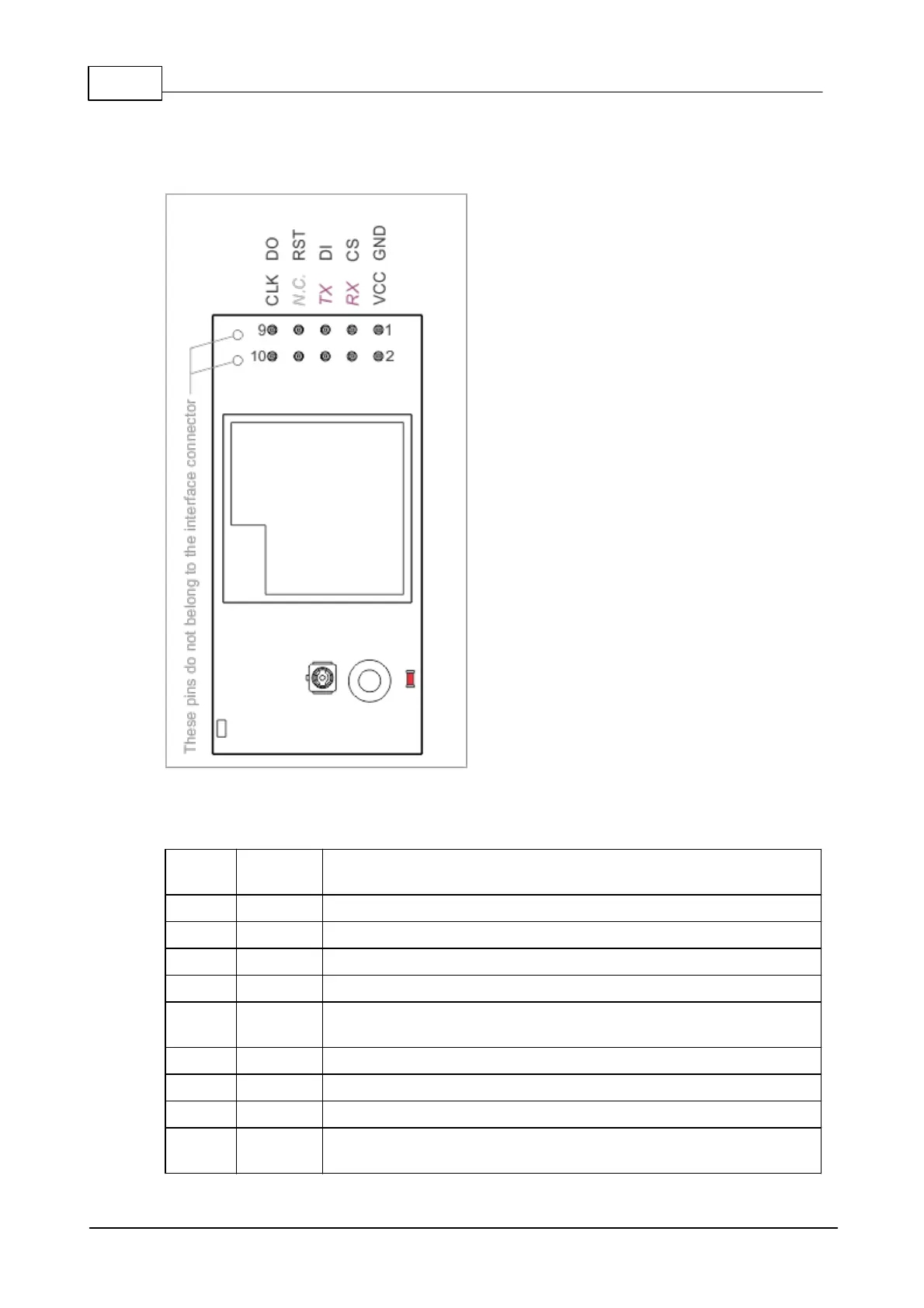
Connector Pin Assignment
I/O pin assignment
Pin #
Functio
n
Description
1
GND
System ground.
2
VCC
Positive power input, 3.3V nominal, +/- 5%.
3
CS
Chip select, active LOW (input*).
4
RX
UART, receive line (input*).
5
DI
SPI port, data in (input*, must be connected to DO of Tibbo
module).
6
TX
UART, transmit line (output*).
7
RST
Reset, active LOW (input*).
8
N.C.
No connection.
9
DO
SPI port, data out (output*, must be connected to DI of
Tibbo module).

Table of Contents

Questions and Answers:

Question and Answer IconNeed help?

Do you have a question about the Tibbo EM1000 and is the answer not in the manual?

Tibbo EM1000 Specifications

General IconGeneral
BrandTibbo
ModelEM1000
CategoryControl Unit
LanguageEnglish