147 Programmable Hardware Manual (PHM)
© Tibbo Technology Inc.
·
GPIO 48 is the Data line; set it to the state that you wish the LED to be in, LOW
= ON, HIGH = OFF.
·
When you then pull GPIO 47 (Clock line) from its normal state (HIGH) to LOW and
then back to HIGH, the state of the Data line is read in and used for LED1.
·
If you want to turn on LED2 (for example) you have to set GPIO 48 to LOW,
toggle the clock once (HIGH-LOW-HIGH) which would set LED1 ON, set GPIO48 to
HIGH (because you want LED1 off) and then just toggle the clock again (HIGH-
LOW-HIGH). At this point, the state of LED1 would shift to LED2 (so LED2 would
light up).
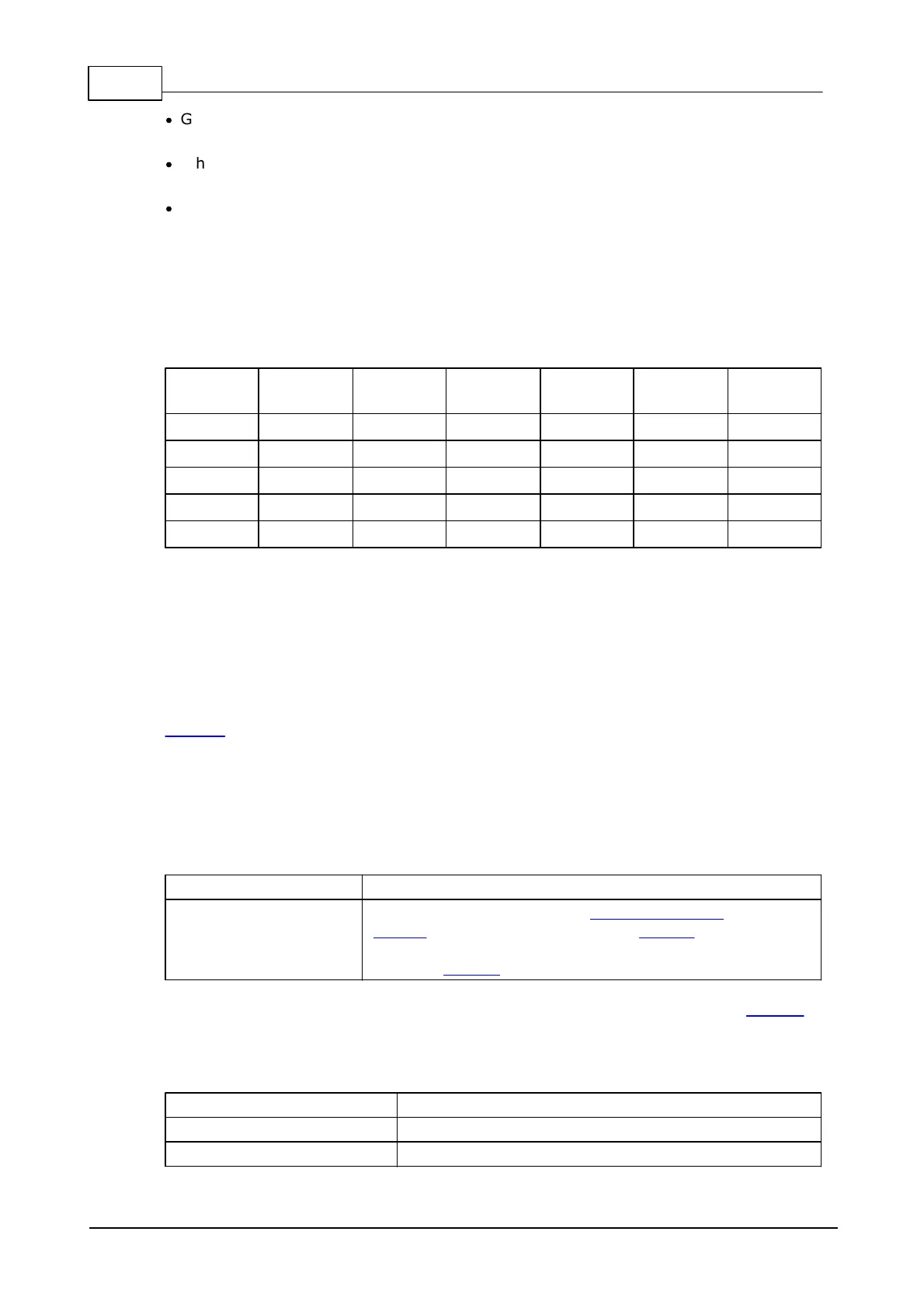
So assuming that all LEDs are OFF and each row means that we have toggled
through one clock cycle:
As you can see, each clock cycle sets a new state for LED1 which directly
corresponds to the state of the Data line, and shifts all previous LED states.
Buzzer
The buzzer of the NB1000 is connected to the GPIO45/CO line of the onboard
EM1000.
Your application can control the buzzer through the "beeper" (beep.) object (see
TIDE, TiOS, Tibbo BASIC, and Tibbo C Manual). Recommended value for the
beep.divider property is 21600.
Ordering Info and Specifications
The NB1000 board with the EM1000-1024K-S module,
IB1000 interboard connector, and LB1000 LED board
mounted on the NB1000 and connected to the latter
with the LC1000 cable.
If you wish to have Wi-Fi or GPRS ports on the NB board, please order the NB1010
product.
Hardware specifications
10/100BaseT Ethernet, Auto-MDIX
 Loading...