455 Programmable Hardware Manual (PHM)
© Tibbo Technology Inc.
TX2 (output,
commonly RTS)
TX2+ (output,
commonly RTS+)
RX2+ (input,
commonly CTS+)
RX2- (input,
commonly CTS-)
Each logical serial port of the ser. object also support RTS/CTS flow control, which
is implemented in firmware (TiOS). Ser.rtsmap and ser.ctsmap properties allow you
to assign any GPIO line of the DS1102 to serve as the RTS or CTS line of any logical
serial port. So, TX2 and RX2 lines (pins 7 and 8) can be assigned to work as RTS
and CTS lines, as is traditionally the case for RS232 ports. At the same time, these
lines can be turned to function as an independent serial channel.
The same goes for the DTR and DSR lines, except they don't even "exist" from the
ser. object's perspective. These lines are implemented on the application level. For
example, our own "serial-over-IP" application supports these lines. Again, instead of
using TX3 and RX3 (pins 4 and 6) as the lines of an independent serial channel, it is
possible to use them as DTR and DSR lines, as is common.
To simplify the discussion, let's look at the serial port from the serial-over-IP
application's point of view. This application defines 15 mapping options. Even in the
RS232 mode, some options are redundant on the DS1102 (but not on the DS1101).
Many more options are redundant in the RS422 mode. See the links below to explore
further:
Mapping options for the RS232 mode
Mapping options for the RS422 mode
And where are mapping options for the RS485 mode? There are none -- but you
knew this already.
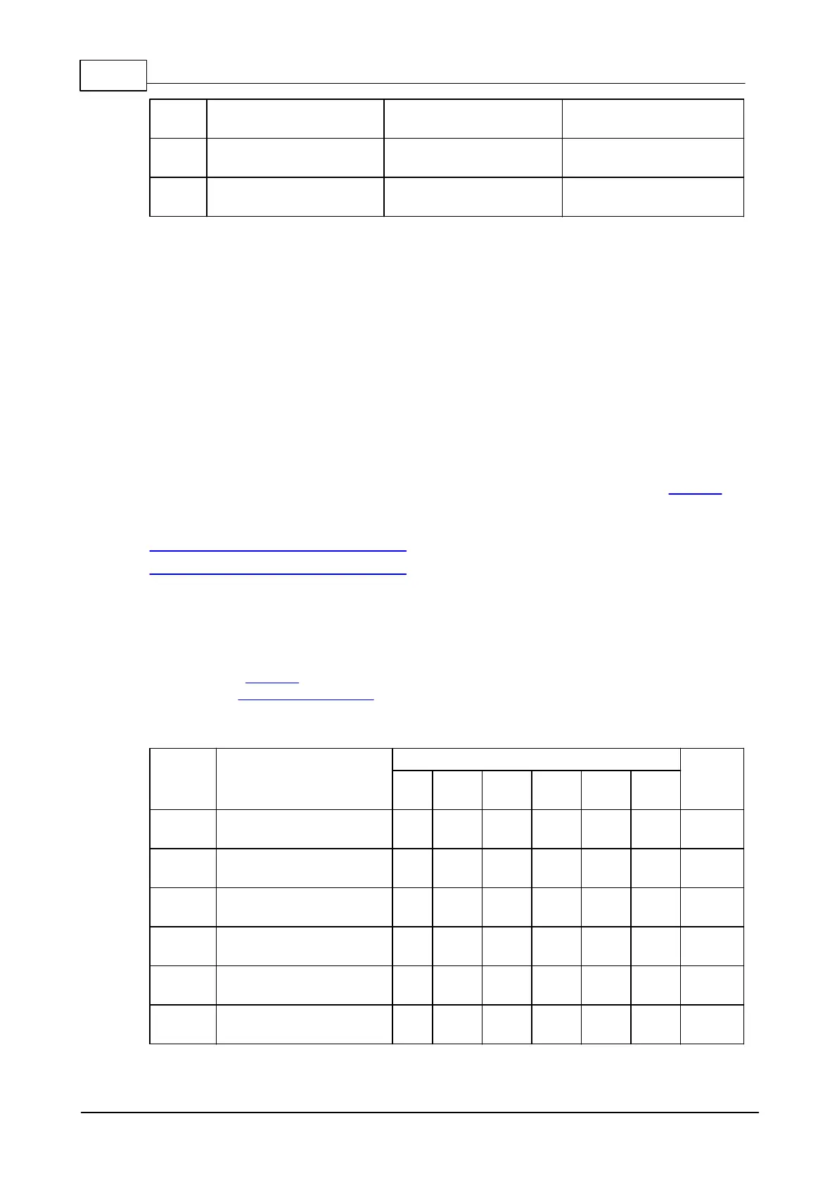
Mapping Options for the RS232 Mode
Unlike on the DS1101 device, the DS1102 does not have an input on line 1. Hence,
some of the 15 mapping options become indistinguishable from other options. Only
"unique" options are shown in the table below.
Pins on the DB9M connector
 Loading...