68Embedded Modules
© Tibbo Technology Inc.
Another group of pins that will be configured and controlled automatically are the
pins responsible for communicating with the external flash IC. When the flash disk
(fd.) object is enabled, GPIO1, GPIO3, and GPIO4 are automatically handled by TiOS
and your application should not attempt to manipulate these lines at the same time.
The fd. object is enabled in the Project Settings dialog of Tibbo IDE software. To
enable, click on the Customize button (of the Project Settings dialog) and set "Flash
disk (fd.) object" to "Enabled."
Note that the interface lines of the WA2000 must be enabled in your code, as this
will not happen automatically. For more information see Connecting WA2000 to
Tibbo Devices.
For more information on fd., bt., ser., io., and other objects, see the TIDE, TiOS,
Tibbo BASIC, and Tibbo C Manual. Additionally, see the Platform-dependent
Programming Information section inside the EM510 platform documentation (same
manual).
4.4.1.2
Ethernet Port Lines
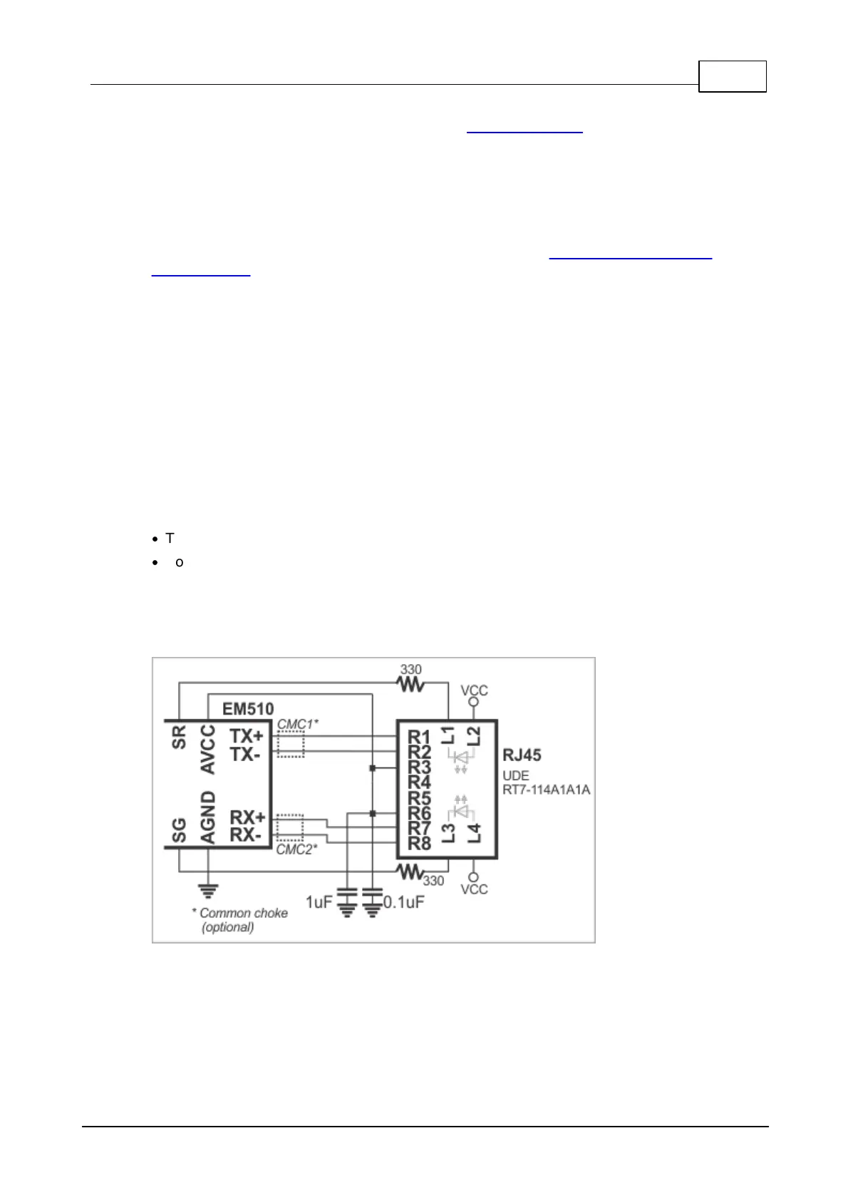
The EM510 has a 10/100BaseT Ethernet port. The onboard electronics of the EM510
do not include Ethernet magnetics, so the magnetics circuitry must be connected
externally to pins TX+, TX-, RX+, RX-, and AVCC. The AVCC pin outputs clean
power for the magnetics circuitry, which is very sensitive to noise.
Please, note the following:
·
The AVCC is an output!
·
Do not combine the AVCC with the VCC (main power) pin.
You can use either a standalone magnetics part, or an RJ45 jack with integrated
magnetics (recommended). Here is a circuit diagram based on the UDE RT7-
114A1A1A part:
It is important to make the PCB wire connections between the pins of the EM510
and RJ45 jack (magnetics circuitry) as short as possible. Making the wires too long
may cause the noise level generated by your PCB surpass the maximum radiated
emission limits set by FCC/CE regulations. Additionally, longer Ethernet lines on the
PCB will make Ethernet operation less stable.
 Loading...