78Embedded Modules
© Tibbo Technology Inc.
4.5.1.1
Serial Port and General-purpose I/O Lines
The EM500 has eight general-purpose I/O lines GPIO0-7 grouped into a single 8-bit
GPIO port P0, plus one serial port.
GPIO0 and GPIO1 lines double as interrupt inputs INT0 and INT1.
The serial port has four I/O lines: RX, TX, CTS, and RTS. TX and RX lines belong
exclusively to the serial port and are separate from the GPIO lines. CTS and RTS
lines do not exist independently. Rather, either GPIO0/INT0 or GPIO1/INT1 can be
selected to serve as the CTS line, while any of the GPIO0-7 lines can be selected to
serve as the RTS line.
The serial port of the EM500 can work in one of the three modes: UART, Wiegand,
or clock/data. TX, RX, CTS, and CTS lines have different names and functions in the
Wiegand and clock/data modes. Serial port operation is described in detail in the
documentation for the serial (ser.) object found inside the TIDE, TiOS, Tibbo BASIC,
and Tibbo C Manual. Additionally, see the Platform-dependent Programming
Information section inside the EM500 platform documentation (same manual).
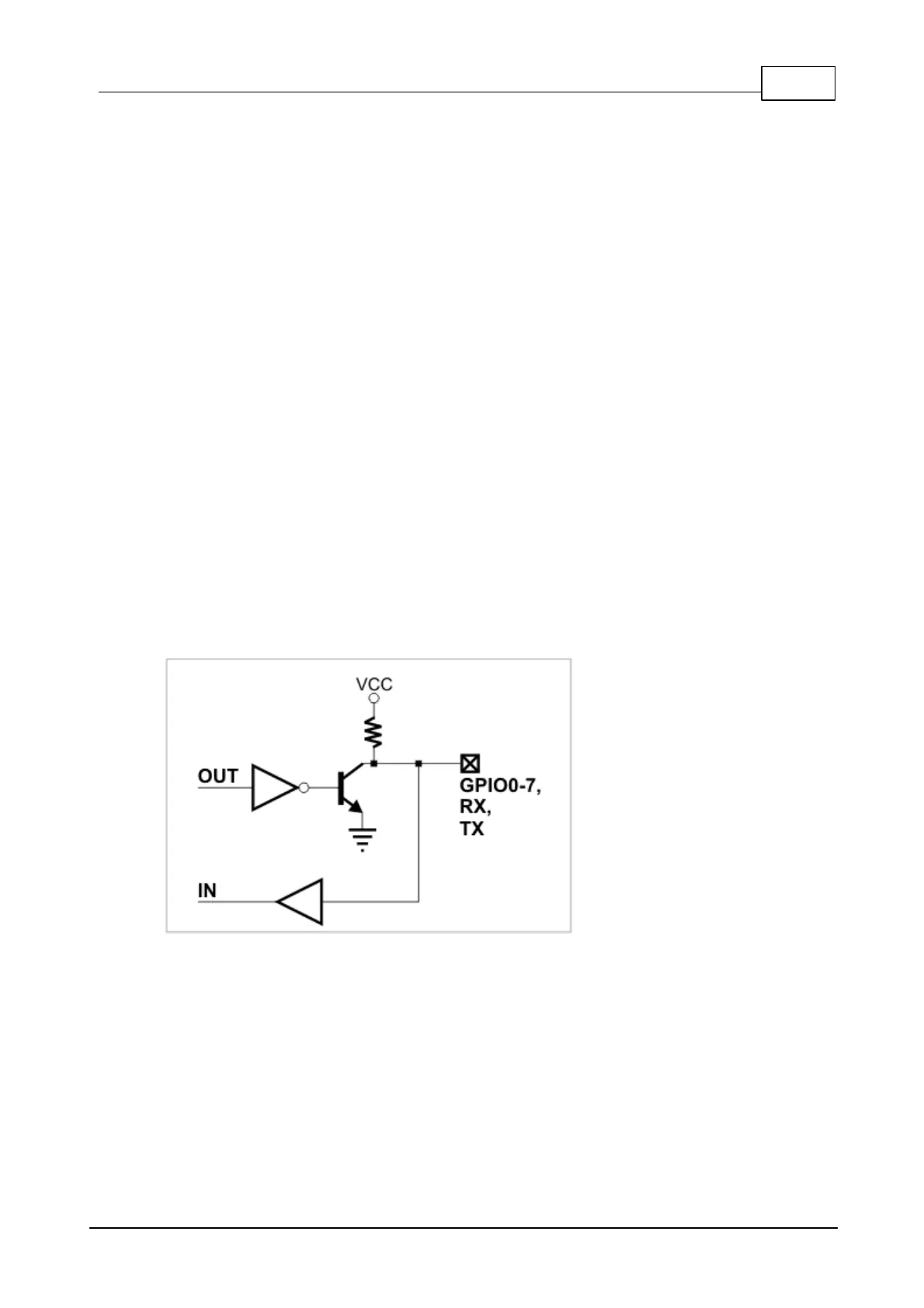
In total, the EM500 has ten I/O lines (GPIO0-7, TX, RX). The simplified structure of
one such I/O line is shown on the circuit diagram below. All lines are "quasi-
bidirectional" and can be viewed as open collector outputs with weak pull-up
resistors. There is no explicit direction control. To "measure" an external signal
applied to a GPIO line, set this line to HIGH first, then read the state of the pin. It is
OK to drive the pin LOW externally when the pin outputs HIGH internally.
Each I/O line has a weak pull-up resistor that prevents the line from floating when
the output transistor is closed. All I/O lines are 3.3V, CMOS, 5V-tolerant. The
maximum load current for each line is 10mA.
I/O line control is described in detail in the documentation for the I/O (io.) object
found inside the TIDE, TiOS, Tibbo BASIC, and Tibbo C Manual.
4.5.1.2
Ethernet Port Lines
The EM500 has a 10/100BaseT Ethernet port. The onboard electronics of the EM500
do not include Ethernet magnetics, so magnetics circuitry must be connected
externally to pins TX+, TX-, RX+, RX-, and AVCC. The AVCC pin outputs clean
power for the magnetics circuitry, which is very sensitive to noise.
Please, note the following:

 Loading...