77 Programmable Hardware Manual (PHM)
© Tibbo Technology Inc.
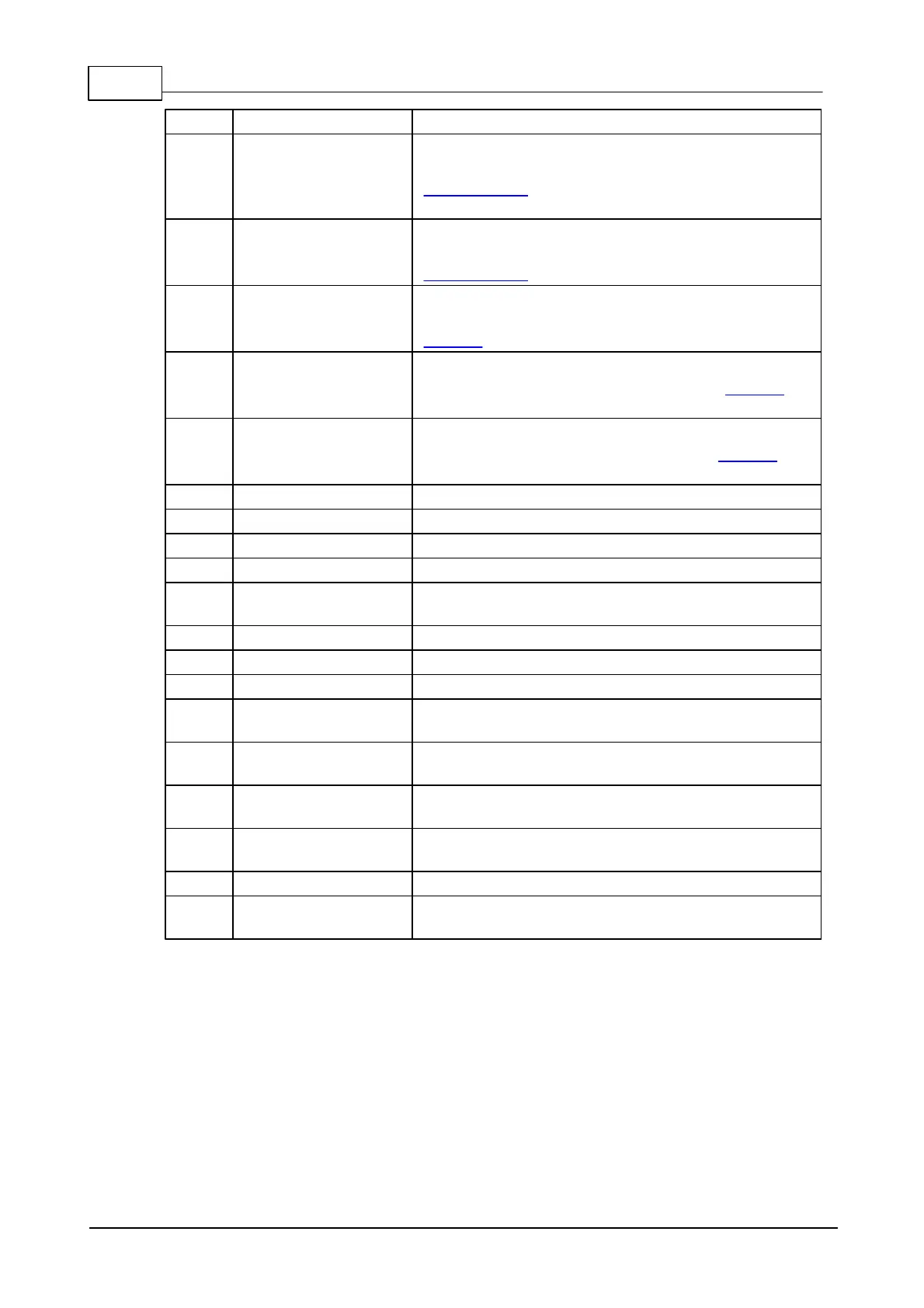
General-purpose I/O line 2 (P0.2).
General-purpose I/O line 3 (P0.3);
for flash disk operation, connect to CLK of
external flash, also connect to 5.1K pull-up
resistor to VCC (3.3V).
General-purpose I/O line 4 (P0.4);
for flash disk operation, connect to CS of
external flash.
General-purpose I/O line 5 (P0.5);
for Wi-Fi operation, connect to DI and DO of
GA1000.
General-purpose I/O line 6 (P0.6);
for Wi-Fi operation, connect to CLK of GA1000,
also to reset-generating logic (NAND gates).
General-purpose I/O line 7 (P0.7);
for Wi-Fi operation, connect to CS of GA1000,
also to reset-generating logic (NAND gates).
RX, W1, and din input of the serial port.
TX, W1, and dout output of the serial port.
Reset input, active low. Proper external reset is a
must.
Link status LED control line.
Dual-function red status LED control line.
Dual-function green status LED control line.
Ethernet port, negative line of the differential
input signal pair.
Ethernet port, positive line of the differential
input signal pair.
Ethernet port, negative line of the differential
output signal pair.
Ethernet port, positive line of the differential
output signal pair.
"Clean" power output for magnetics circuitry.
Positive power input, 3.3V nominal, +/- 5%, max.
current consumption 260mA.
Notes:
1. This line is 5V-tolerant and can be interfaced to 5V CMOS devices directly.
2. This line can serve as an RTS/Wout/cout line of a serial port (provided that this
does not interfere with any other function).
3. This line can serve as a CTS/W0&1in/cin line of a serial port (provided that this
does not interfere with any other function).
 Loading...