411 Programmable Hardware Manual (PHM)
© Tibbo Technology Inc.
·
Buzzer
·
LCD Display Connector (TPP2 only)
·
Keypad Connector (TPP2 only)
·
Optional Wi-Fi
Power Arrangement
The TPP2 can be powered directly through two terminal blocks located next to the
RJ45 jack. The board expects regulated +5V power. We recommend the power
supply with at least 1-1.5A output current capability. 300mA of this power budget
will be used for the TPP2 alone. The WA2000 Wi-Fi add-on, if present, will consume
an additional 300mA of current. Installed Tibbits will also add to the overall power
consumption.
Alternatively, the TPP2 can be powered using power supply Tibbits (such as #9,
#10, #23, etc.), in which case there will be no need to connect +5V power to the
board.
Some Tibbits (such as #13 or #14) require additional +15V and -15V power to
function. These voltages are not generated by the TPP2 and can't be applied
externally. The only way to produce them is to install a special power Tibbit #12.
The Tibbit Power Lines topic contains additional information on the subject.
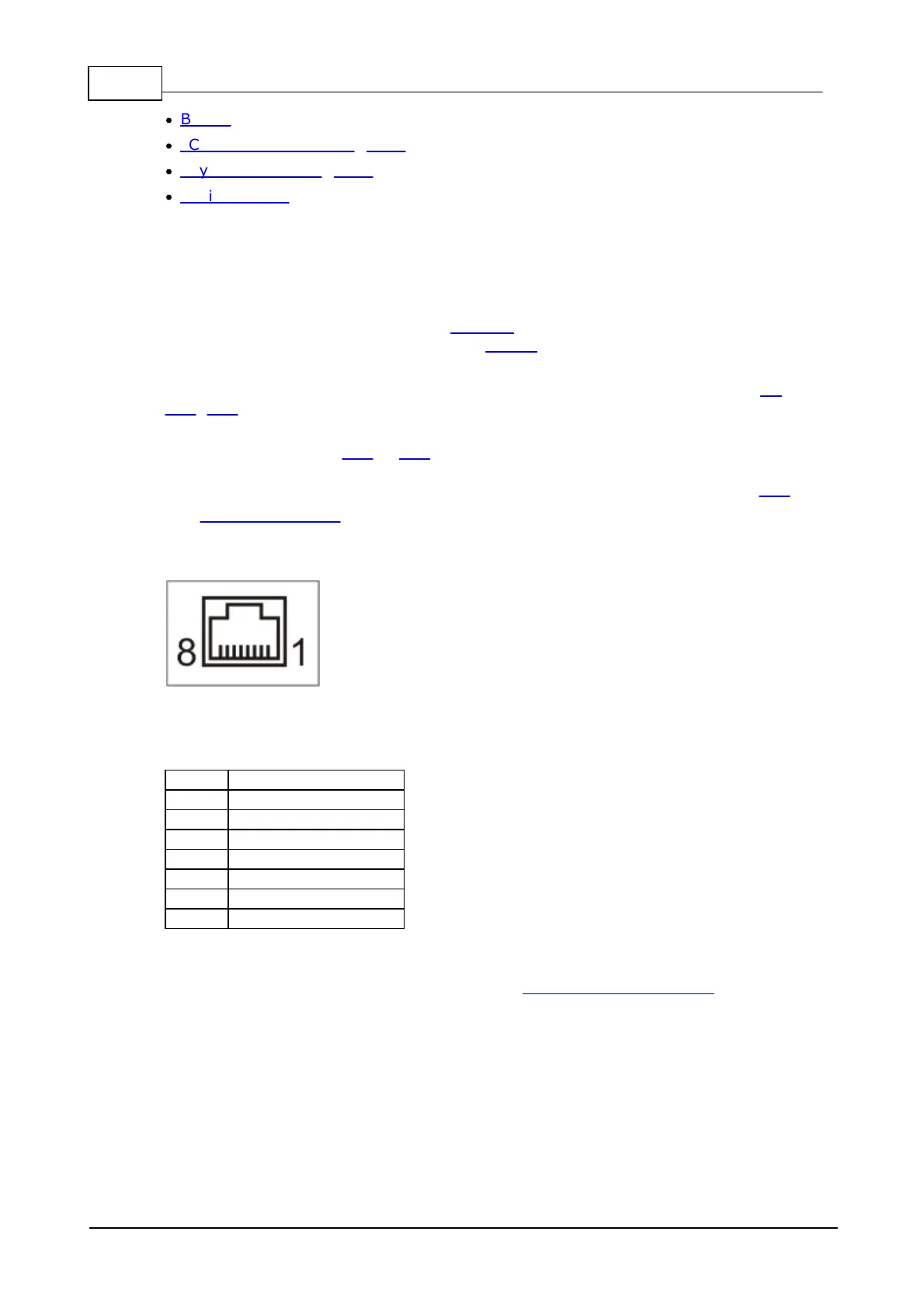
Ethernet Port
The Ethernet port of the TPP2 is of 10/100BaseT type.
The connector is of RJ45 type, pin assignment is as follows:
MD and RST Buttons
The function of the MD button is described in Setup (MD) Button (line).
Pressing the reset button causes a hardware reset.
Both buttons face right on Tibbo Project PCBs. For assembly inside a Tibbo Project
Box (TPB), a TPP must be outfitted with a so-called MD/RST button PCB. This is a
small PCB with two buttons facing upward. When plugged into the TPP board, these
buttons work in parallel with the buttons of the TPP board.
The MD/RTS PCB is necessary only when you assemble the TPP board into the Tibbo
Project Box. Hence, the MD/RST PCB is supplied as a part of the TPB kit, not the
Tibbo Project PCB.
 Loading...