178Boards
© Tibbo Technology Inc.
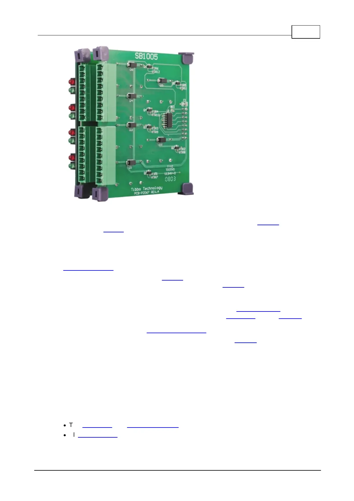
The IB1005 is the main board in the pair, and is connected to an NB10x0 network
board by the IB1000 interboard cable. The SB1005 is a supplementary board, it
exists because a single IB1005 would not be able to accommodate all required
circuitry and terminal blocks. In the board pair, the IB1005 carries isolated digital
inputs and the RS232/485, while the SB1005 contains all relays.
The IB1005 and SB1005 are not meant to be used separately and should always be
ordered together.
The IB1005 product includes the LB1001 LED board. The IB1005 and the LB1001
come assembled together and interconnected by the LC1000 cable. Therefore, you
don't need to order the LB1001 and LC1000 separately when purchasing the IB1005
board.
All I/O lines of the IB1005 + SB1005 are grouped into four terminal blocks (two per
board), with 9 terminals in each block. The boards are controlled by the EM1000
module located on the NB10x0 board. More information on specific IB1005 + SB1005
functionality is found in the Detailed Information section.
To simplify testing and evaluation of the product use the TB1005 test board.
Terminal Blocks
The IB1005 and the SB1005 have four terminal blocks between them. There are nine
terminals in each block.
·
The serial port and sensor input lines are grouped into terminal blocks 1 and 2.
·
All relay outputs are on terminal blocks 3 and 4.
 Loading...