252Development Systems
© Tibbo Technology Inc.
Connection to the WA2000 is implemented according to the schematic diagram in
the Connecting WA2000 to Tibbo Devices topic. Note that the WA2000 is only
supported by the EM510 module.
Connection to the flash memory is implemented according to the schematic diagram
presented in the Flash and EEPROM Memory topic (of the EM510 documentation).
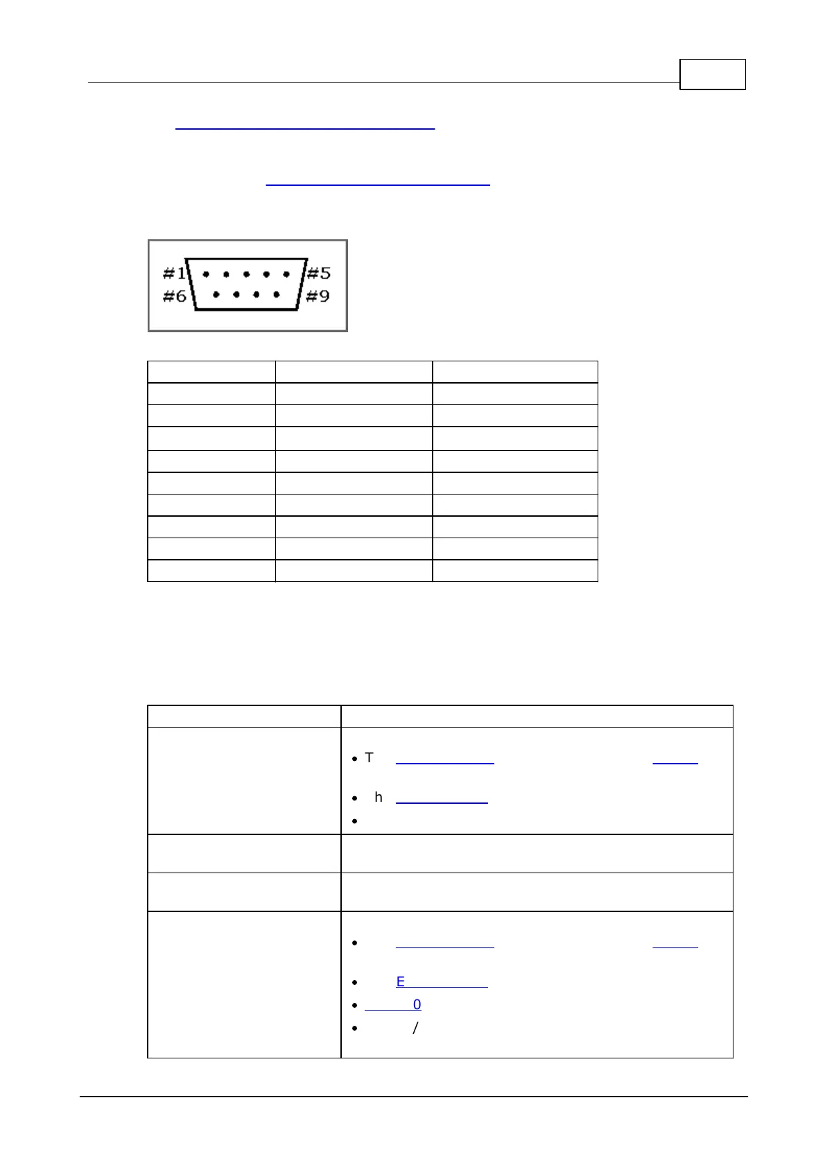
RS232 interface lines are available on a standard DB-9M connector:
Ordering Info
Ordering codes for complete Development Systems
EM500 development system, includes:
·
The EM500EV-MB0 motherboard with the EM510
module on a socket.
·
The EM500EV-IB0 interface board.
·
No power adapter.
Same as EM510EV-R, but with an EU type 12V power
adapter included.
Same as EM510EV-R, but with a US type 12V power
adapter included.
EM510 development system, includes:
·
The EM500EV-MB0 motherboard with the EM510
module on a socket.
·
The EM500EV-IB2 interface board.
·
WA2000 Wi-Fi/BLE add-on.
·
2.4GHz/5GHz antenna with cable.
 Loading...