520Companion Products
© Tibbo Technology Inc.
Ethernet port, positive line of the differential
output signal pair
Ethernet port, negative line of the differential
output signal pair
Interfacing the RJ203 to the DM9000B
The RJ203 module interfaces directly to the DAVICOM's DM9000B Ethernet
controller. The following table details the interconnection between the DM9000A and
the interface pads of the RJ203:
Don't forget to connect grounds too!
Additional passive components, such as resistors and capacitors must also be
placed near the DM9000B and connected to RX and TX lines. For detailed
information see the DM9000B datasheet.
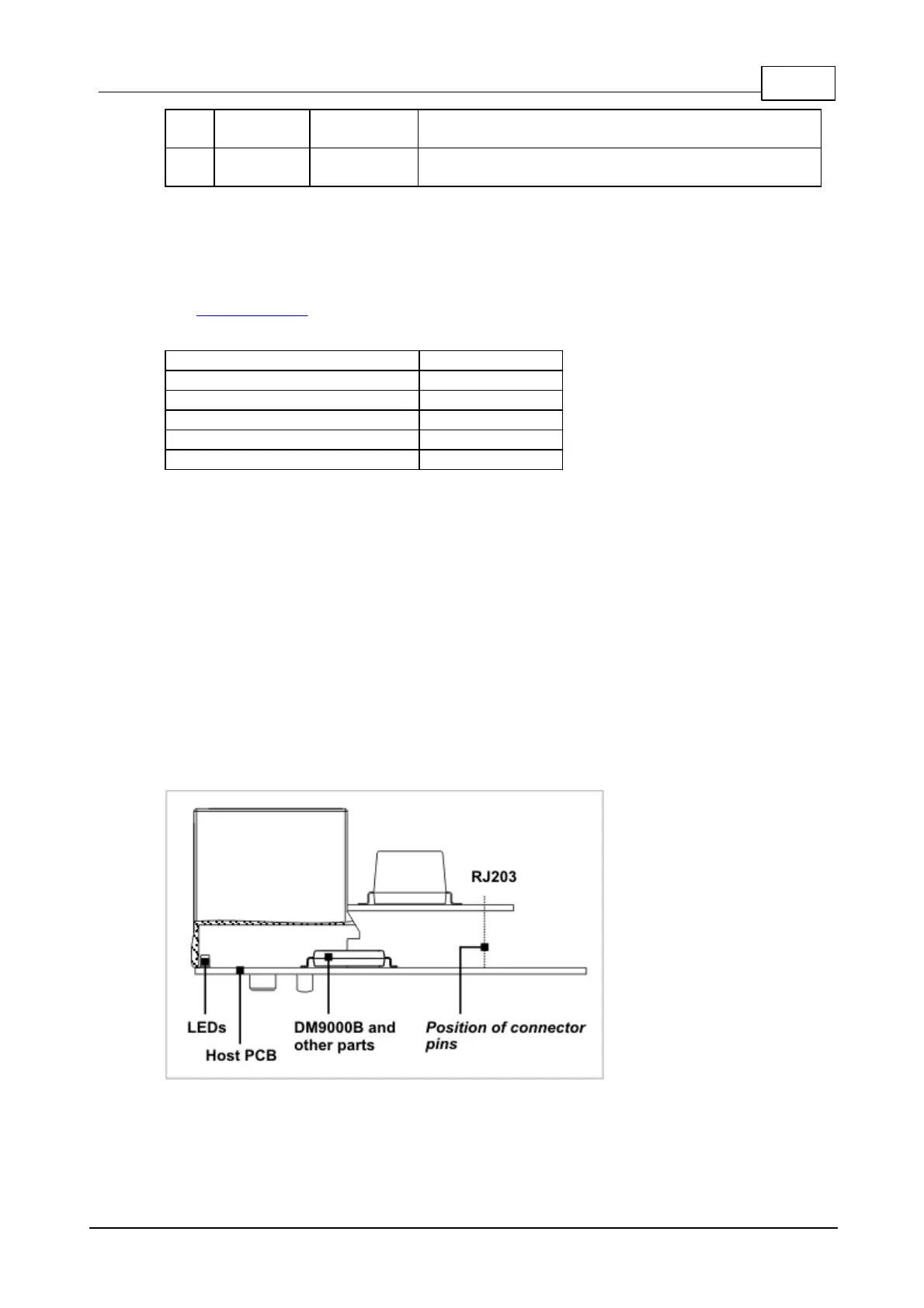
To take full advantage of the unique space-saving design of the RJ203, place the
DM9000B (and/or any other components as you see fit) under the module. The
housing of the module has a substantial recess area under the RJ45 jack. This area
can be utilized to accommodate various board components. Moreover, the housing
of the RJ203 is made of a translucent material, so you can also place necessary
status LEDs within the recess area and in the proximity to the front wall of the
RJ203. This way, your status LEDs will be visible through the translucent front face
of the RJ203. Four to six LEDs can easily fit along that front wall.
 Loading...