47 Programmable Hardware Manual (PHM)
© Tibbo Technology Inc.
13uA when the EM1000 is not powered (0V on
VCC)
Operating relative humidity
Mechanical dimensions
(excl. leads)
"Plain" EM1000: 38.4x28.4x5.5 mm
EM1000-...-S
(2)
: 38.4x28.4x9.5 mm
EM1000G: 38.4x28.4x11.0 mm
EM1000G-...-S
(2)
: 38.4x28.4x15.0 mm
Plain EM1000 devices: tube, 10 modules/tube
All other variants: tray, 30 modules/tray
Notes:
1. The RTC will not lose its data and will keep running as long as the backup voltage
stays within this range.
2. The EM1000-xxxK-S device cannot be installed on the PCB directly. This is
because it has a supercapacitor mounted on the bottom side of the module. This
device must be be mounted on a socket.
All specifications are subject to change without notice and are for reference only.
Tibbo assumes no responsibility for any errors in this Manual, and does not make
any commitment to update the information contained herein.
Think the above table should contain additional data? Do not just assume that you
know the answer — talk to Tibbo! Remember that the ultimate responsibility for all
decisions you make regarding the use and the mode of use of Tibbo products lies
with you, our Customer.
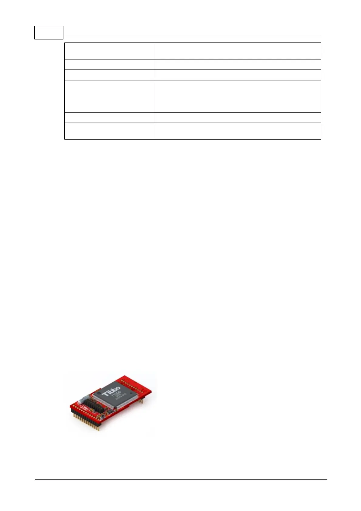
EM1206 BASIC/C-programmable Ethernet
Module
EM1206 module
 Loading...