EasyManuals Logo

Tibbo EM1000 User Manual

Tibbo EM1000
570 pages
To Next Page IconTo Next Page
To Previous Page IconTo Previous Page
Page #232 background imageLoading...
Page #232 background image
221 Programmable Hardware Manual (PHM)
© Tibbo Technology Inc.
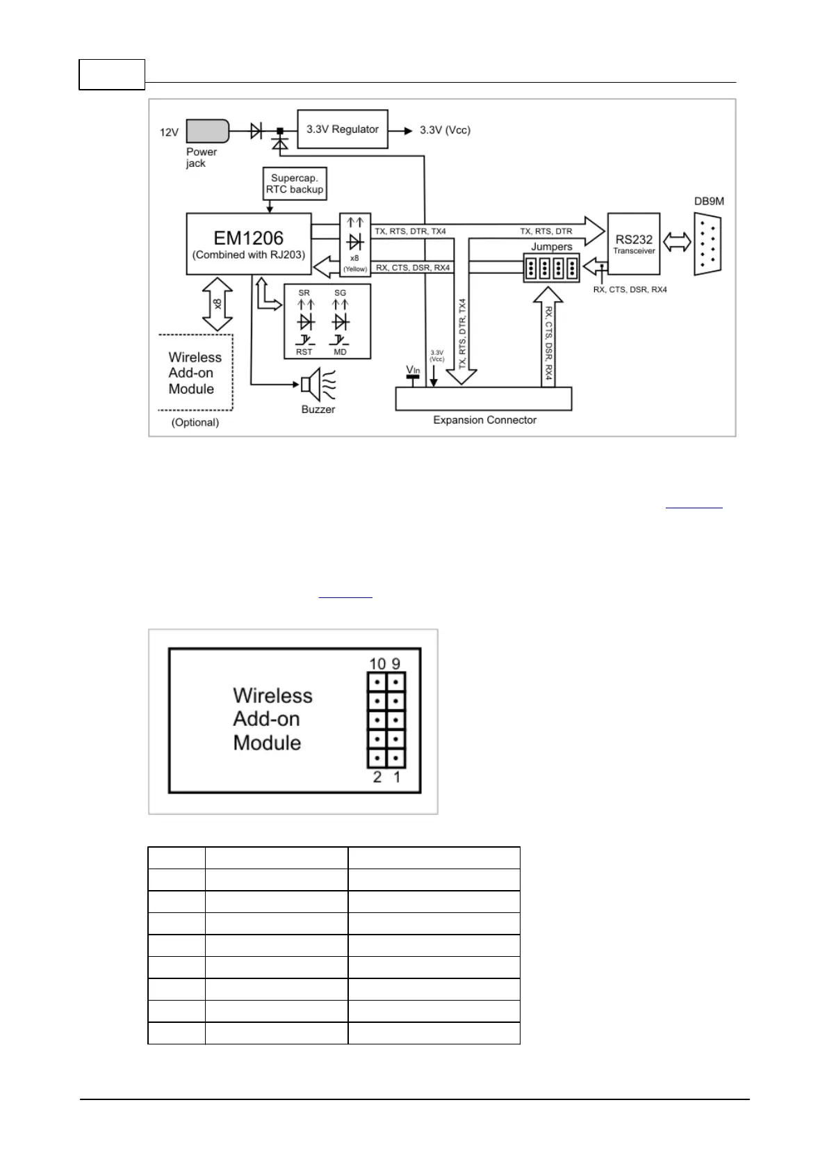
Wireless Add-on Connector
This connector is used to plug in an optional wireless add-on, such as the WA2000
Wi-Fi add-on, as well as other add-on modules that may be released by Tibbo in the
future.
The connector has 10 pins, as shown on the drawing below. Apart from the ground
and Vcc (3.3V) lines, there are eight I/O lines that are connected directly to port 1
(GPIO lines 8-15) of the EM1206.
Pin
EM1206 line
WA2000 line
#1
GND
GND
#2
Vcc (3.3V)
Vcc (3.3V)
#3
GPIO15/P1.7
CS
#4
GPIO10/P1.2
---
#5
GPIO13/P1.5
DO
#6
GPIO9/P1.1
---
#7
GPIO11/P1.3
RST
#8
GPIO8/P1.0
---

Table of Contents

Questions and Answers:

Question and Answer IconNeed help?

Do you have a question about the Tibbo EM1000 and is the answer not in the manual?

Tibbo EM1000 Specifications

General IconGeneral
BrandTibbo
ModelEM1000
CategoryControl Unit
LanguageEnglish