182Boards
© Tibbo Technology Inc.
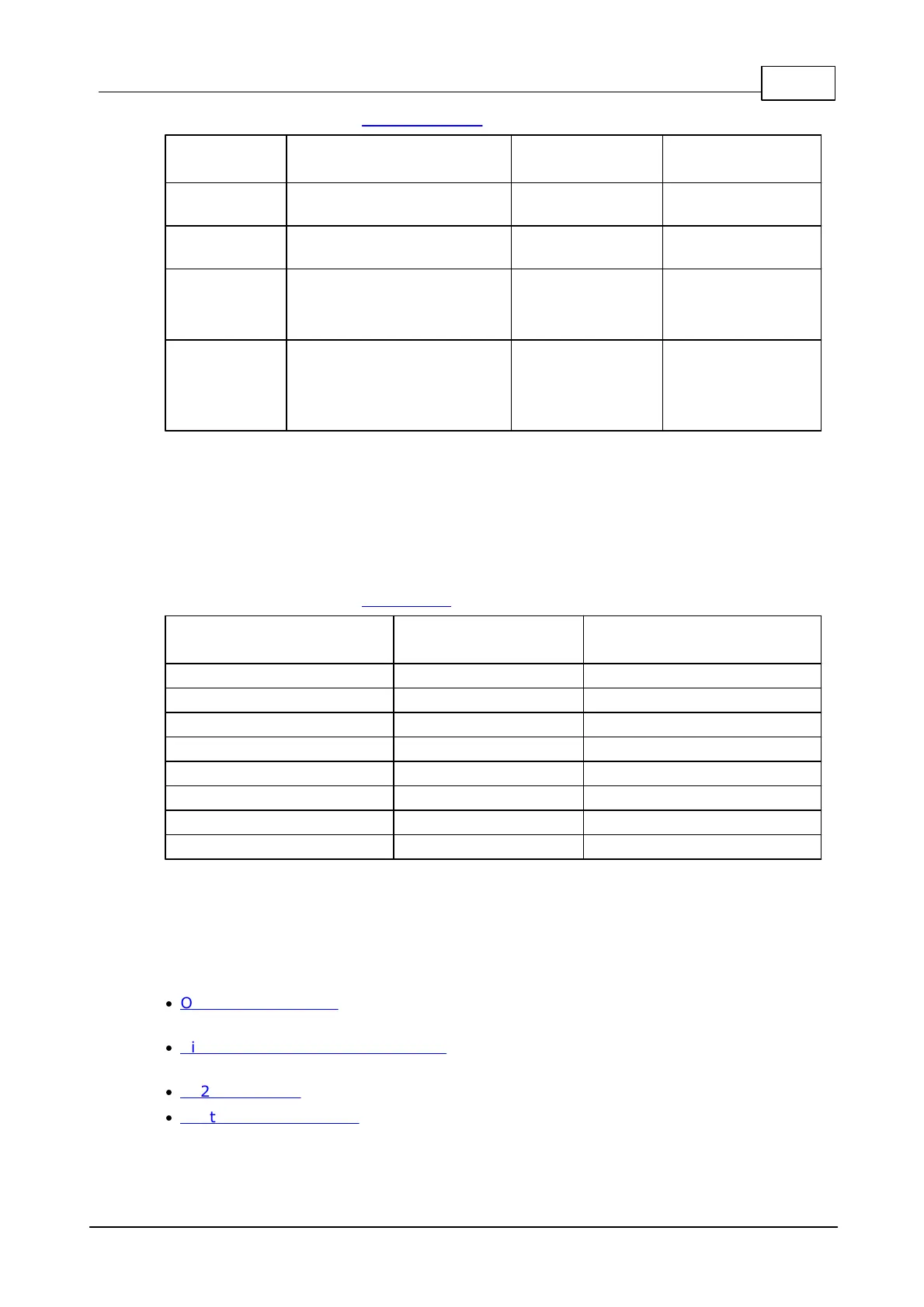
For more information see RS232/485 port.
Receive line of the serial
port
Transmit line of the serial
port
Mode selection:
HIGH - RS485
LOW (or input*) - RS232
Direction control in RS485
mode:
HIGH - output
LOW - input
*GPIO line configured as input (default state)
LED control
For all LED control lines:
HIGH (or input*) - LED off
LOW - LED on
For more information see LED Control.
*GPIO line configured as input (default state)
Detailed Information
The IB1005 includes the following blocks:
·
Opto-isolated inputs (8 in total, 4 can be used to connect two Wiegand or
clock/data readers).
·
Six high-current mechanical relays (both normally-opened and normally-closed
terminals are provided).
·
RS232/485 port (RX/TX signals for the RS232, TX/RX+ and TX/RX- for the RS485).
·
Control lines for 8 LEDs on the LB1001 board (the board must be ordered
separately).

 Loading...