146Boards
© Tibbo Technology Inc.
These are yellow and green LEDs connected to the EY and EG pins of the EM1000.
Further information on status LEDs can be found in Status LEDs.
External LED Control
The NB1000 is intended to be used with the LB1000 board. This board provides:
·
Green and red LED pair.
·
Green and yellow LED pair.
·
LED bar comprising five yellow LEDs.
Green and red LED pair -- system status indication
These LEDs are controlled by the SG and SR pins of the EM1000. Further information
on status LEDs can be found in Status LEDs.
Green and yellow LED pair -- Ethernet status indication
These LEDs are connected to the same EG and EY lines of the EM1000 that control
green and yellow LEDs on the NB1000 board itself.
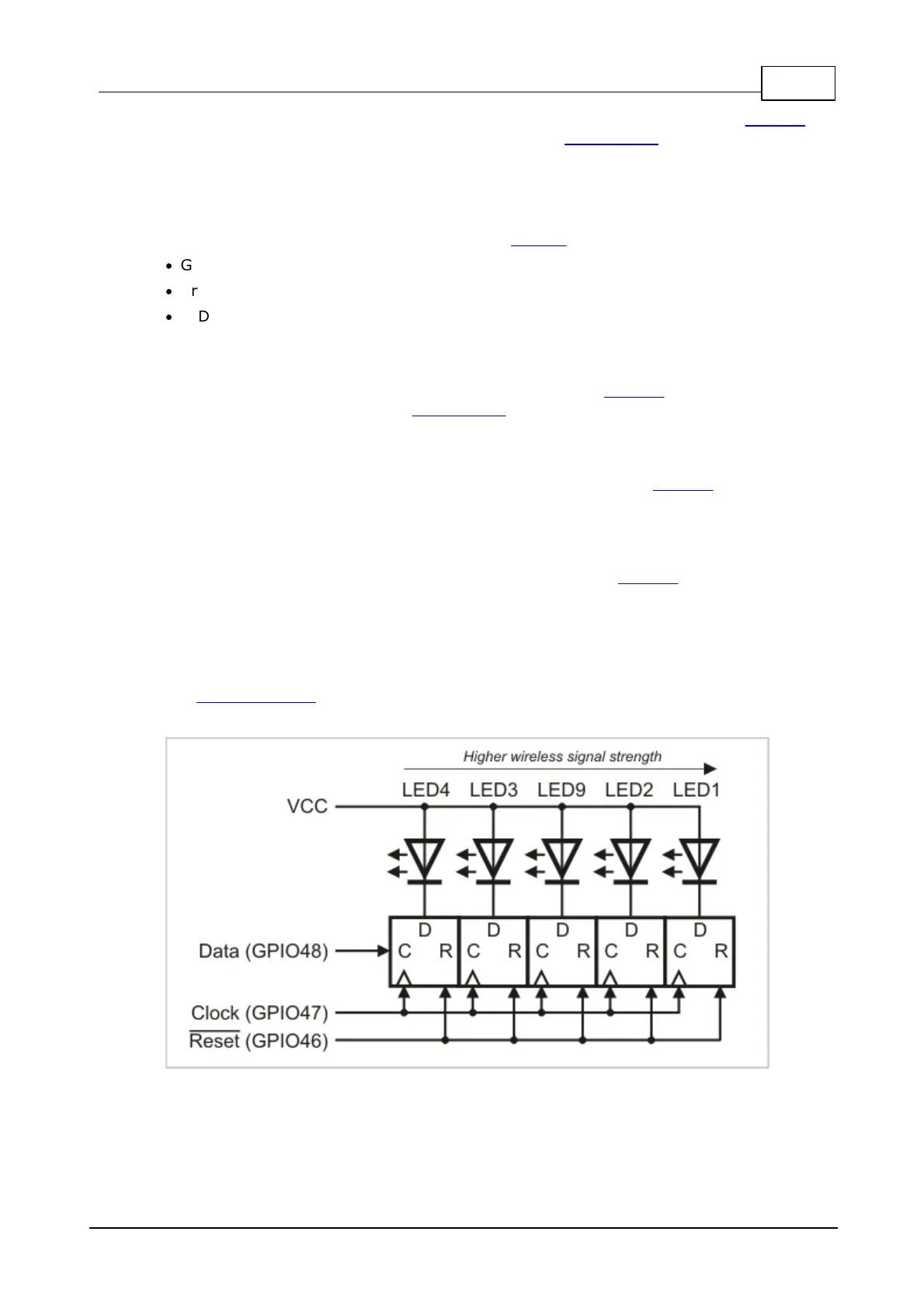
LED bar -- wireless signal strength indication
These LEDs are controlled through three GPIO lines of the EM1000- GPIO46, GPIO47,
and GPIO48.
GPIO46 is the reset line of the LED bar. Clearing this line sets all five outputs to
LOW and this turns all LEDs ON. GPIO47 is a clock line- a positive (LOW-to-HIGH)
transition on this line "shifts in" the data on the GPIO48 line. The circuit that
controls the LEDs is shown below. LED numbers correspond to numbers shown on
the LB100x drawing.
If you want to switch an LED ON then set the data line LOW. The data bit for the
LED#1 (indicating the highest signal strength) is clocked in first. That's the short
explanation. In further detail, we can say:
 Loading...