423 Programmable Hardware Manual (PHM)
© Tibbo Technology Inc.
3.5" 320x240 TFT LCD panel with controller
Keypad PCB for TPB2L, with cable
MD/RST button PCB (all TPB models)
Blank Tibbit shell, C1 form factor, orange
Main Screw (all TPB models)
PCB screw (all TPB models)
The TPB2L can be purchased with an optional DIN rail mounting kit and an available
vibration protection kit (VPK), with which TPS devices meet the shock and vibration
resistance requirements of the IEC 60068-2-27 standard.
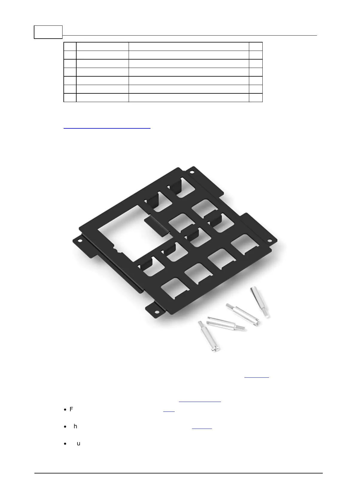
Size 2 Vibration Protection Kit (VPK)
The vibration protection kit (VPK) consists of the vibration protection plate, four
special screws, and two small rubber parts that cushion the WA2000 Wi-Fi add-on,
when installed (they come attached to the plate and are not visible on the above
picture).
The plate is installed as shown on the exploded view of the TPS:
·
Four M2.5 screws securing the TPP are removed and four special screws (shown
above) are instead used to attach the TPP onto the bottom cover;
·
The vibration protection plate goes over Tibbits (installed on the TPP) and rests
on these special screws;
·
Four M2.5 screws that originally held the TPP in place are used to secure the
vibration protection plate onto the special screws.

 Loading...