398Tibbo Project System (TPS)
© Tibbo Technology Inc.
some sockets have a reduced number of control lines, or have no lines connected at
all:
·
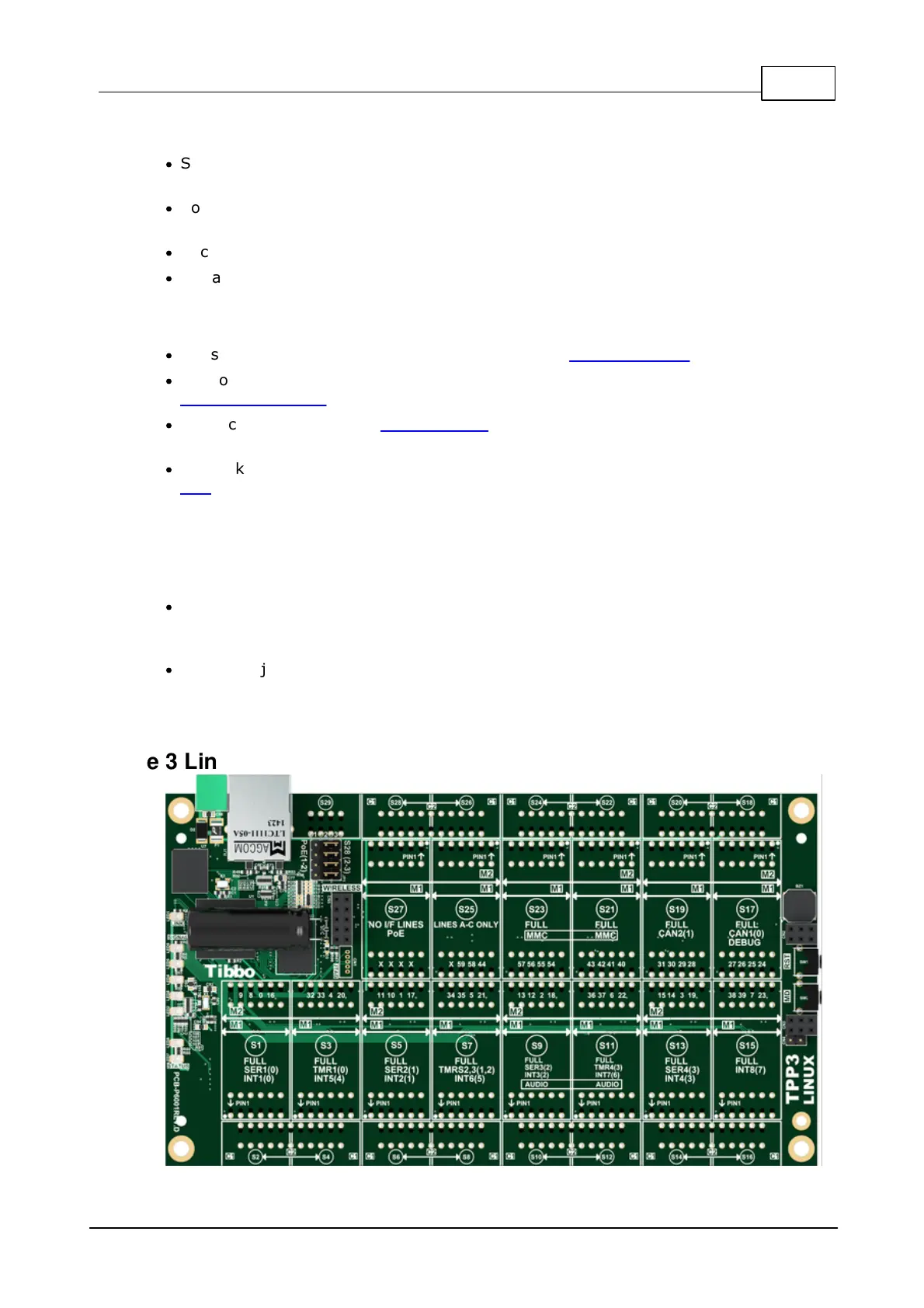
Socket (S23) only has control lines A and B. Control lines C and D are not
implemented.
·
Socket (S25) only has the control line A. Control lines B, C, and D are not
implemented.
·
Socket (S27) has no control lines connected to it.
·
Remaining "M" sockets have all four control lines implemented.
Additionally:
·
"M" sockets (S1), (S5), (S9), and (S13) have the UART capability.
·
"M" sockets (S1), (S3), (S5), (S7), (S9), (S11), (S13), and (S15) have the
interrupt capability.
·
"M" socket (S27) has the PoE capability, provided that four TPP2 jumpers are set
to 2-3 position (see below).
·
"C" socket (S29) exists exclusively for the installation of the RF connector Tibbit
#37. This socket has no other functions.
The jumpers
Four jumpers next to the RJ45 jack define the connection between the "M" socket
(S27), "C" socket (S28), and the RJ45 jack:
·
When the jumpers are in the 1-2 position, four power lines from the RJ45 jack are
connected to four I/O lines of (S27). Under this arrangement you can install an M1
PoE device into the (S27), or M2 PoE device into the (S25)-(S27).
·
When the jumpers are in the 2-3 position, the RJ45 jack is disconnected from the
socket (S27). The socket (S27) is instead connected to (S28) in a "standard tile
way".
7.3.1.5
Size 3 Linux Tibbo Project PCB (LTPP3)

 Loading...