394Tibbo Project System (TPS)
© Tibbo Technology Inc.
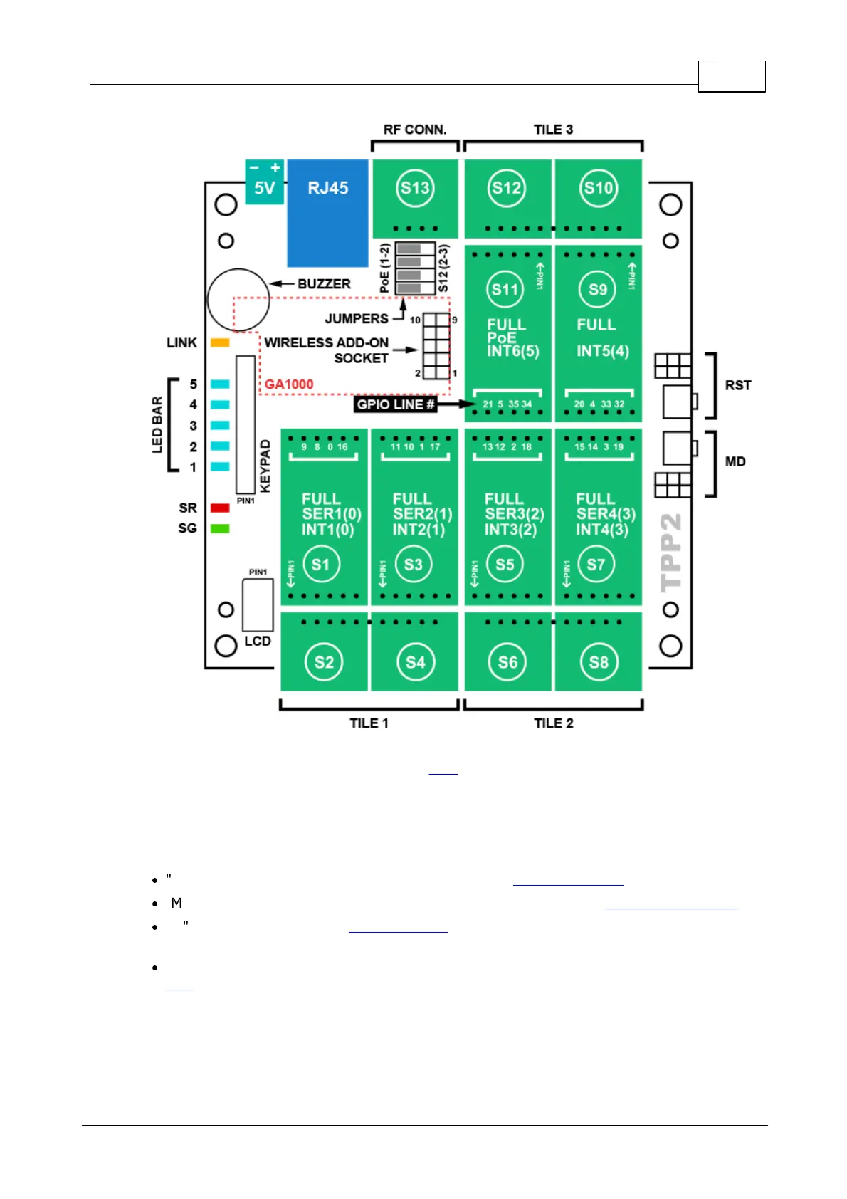
Tiles, Sockets, Connectors, Controls
The TPP2 board features 6 x "M" and (6+1) x "C" sockets.
Sockets (S1) ~ (S12) form 3 standard tiles.
There are 24 control lines connecting "M" sockets to the CPU -- four per each
socket.
Additionally:
·
"M" sockets (S1), (S3), (S5), and (S7) have the UART capability.
·
"M" sockets (S1), (S3), (S5), (S7), (S9), and (S10) have the interrupt capability.
·
"M" socket (S11) has the PoE capability, provided that four TPP2 jumpers are set
to 1-2 position (see below).
·
"C" socket (S13) exists exclusively for the installation of the RF connector Tibbit
#37. This socket has no other functions.
The jumpers
Four jumpers next to the RJ45 jack define the connection between the "M" socket
(S11), "C" socket (S12), and the RJ45 jack:
 Loading...