EasyManuals Logo

Tibbo EM1000 User Manual

Tibbo EM1000
570 pages
To Next Page IconTo Next Page
To Previous Page IconTo Previous Page
Page #534 background imageLoading...
Page #534 background image
523 Programmable Hardware Manual (PHM)
© Tibbo Technology Inc.
h1
Aver
.
17.5
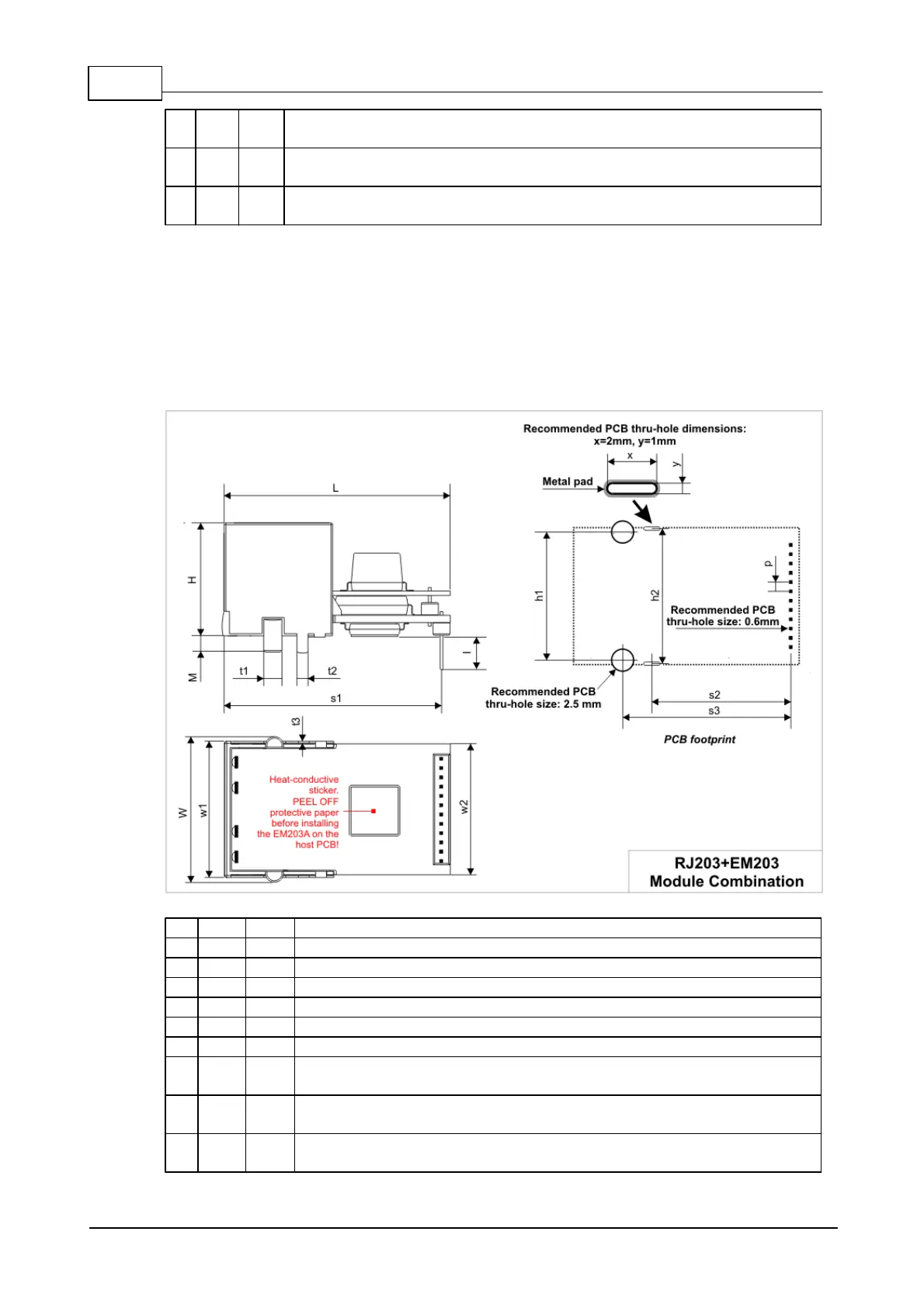
Distance between the horizontal centerlines of mounting stands
h2
Aver
.
18.5
Distance between the horizontal centerlines of solder tails
C
Min.
4.4
Clearance from the installation surface to the top wall of the recess
area of the housing
Dimensions are for reference only. Tibbo assumes no responsibility for any errors in
this Manual, and does not make any commitment to update the information
contained herein.
Mechanical Dimensions: RJ203+EM203
L
Max.
31.0
Length
W
Max.
20.0
Width
H
Max.
15.5
Height
l
Min.
4.0
Connector pin length
w1
Max.
19.0
Width at the face excluding mounting stands
w2
Max.
18.1
Board width
M
Min.
1.9
Mounting stand and tail height
t1
Aver
.
2.5
Mounting stand diameter
t2
Aver
.
1.5
Solder tail width
t3
Aver
.
0.25
Solder tail thickness

Table of Contents

Questions and Answers:

Question and Answer IconNeed help?

Do you have a question about the Tibbo EM1000 and is the answer not in the manual?

Tibbo EM1000 Specifications

General IconGeneral
BrandTibbo
ModelEM1000
CategoryControl Unit
LanguageEnglish