511 Programmable Hardware Manual (PHM)
© Tibbo Technology Inc.
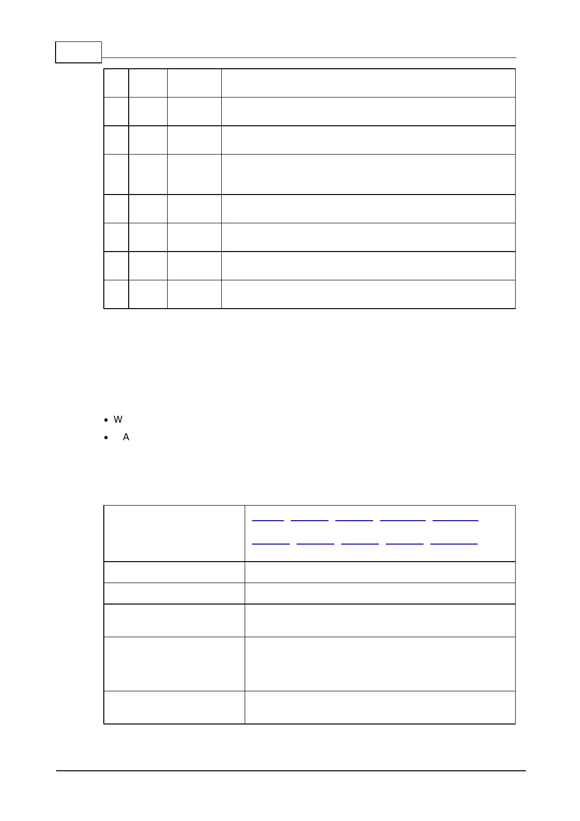
Distance from the first pin row to the top side of the
module
Distance from the centerline to the left side of the
module
Distance from the centerline to the right side of the
module
Distance from the first pin row to the center of the antenna
connector, the center of the mounting hole, and the center of the
status LED
Distance from the centerline to the center of the antenna
connector
Distance from the centerline to the center of the mounting hole
Distance from the centerline to the center of the status LED
Dimensions are for reference only. Tibbo assumes no responsibility for any errors in
this Manual, and does not make any commitment to update the information
contained herein.
Ordering Info and Specifications
The WA2000 device is available in two configurations:
·
WA2000U – U.FL connector for an external antenna.
·
WA2000C – chip antenna onboard.
Specifications
EM510, EM2000, EM2001, TPP2(G2), TPP3(G2) –
support for both Wi-Fi and BLE;
EM1000, EM1001, EM1206, EM1202, DS1101/2 –
support for Wi-Fi only
Nominal power supply
voltage (VCC pin)
Operating current (VCC
pin)
Post-reset, before boot: ~70mA;
Fully functional, no data transmission: ~120mA;
During the data transmission: ~200mA;
Short current consumption bursts up to 500mA.
Operating temperature
range
 Loading...