52Embedded Modules
© Tibbo Technology Inc.
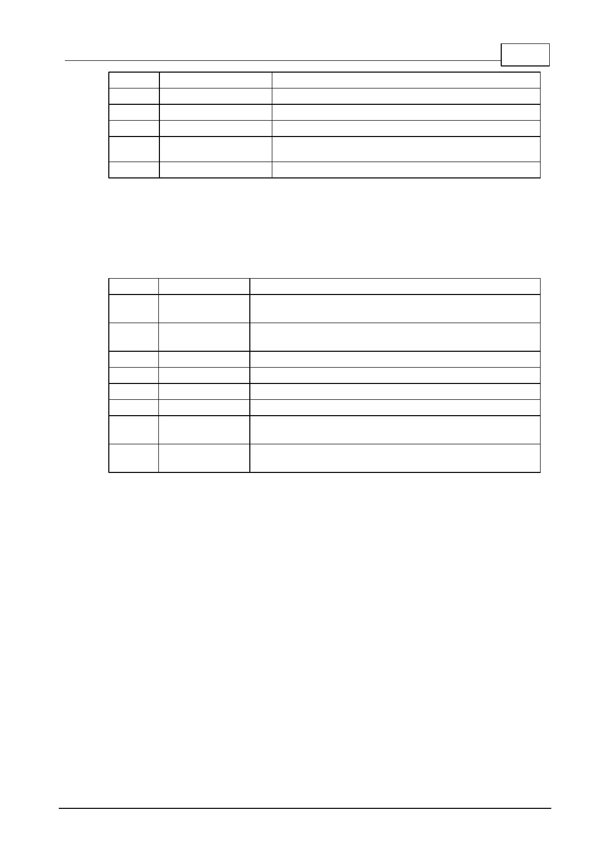
General-purpose I/O line 10 (P1.2).
General-purpose I/O line 11 (P1.3).
General-purpose I/O line 12 (P1.4).
General-purpose I/O line 13 (P1.5).
General-purpose I/O line 14 (P1.6).
General-purpose I/O line 15 (P1.7).
Notes:
1. This line is 5V-tolerant and can be interfaced to 5V CMOS devices directly.
2. This line can be assigned to serve as an RTS/Wout/cout line of a serial port.
Magnetics connector
Ethernet port, positive line of the differential input
signal pair.
Ethernet port, negative line of the differential input
signal pair.
"Clean" 1.8V power output for magnetics circuitry.
Ethernet port, positive line of the differential output
signal pair.
Ethernet port, negative line of the differential output
signal pair.
4.3.1.1
General-purpose I/O Lines
The EM1206 has 17 general-purpose I/O lines (GPIO0 - GPIO16). All lines are 3.3V,
CMOS, 5V-tolerant. Maximum load current for each line is 10mA. Out of seventeen
available lines, sixteen are combined into two 8-bit ports.
The simplified structure of one I/O line of the EM1206 is shown on the circuit
diagram below. Each line has an independent output buffer control. When the
EM1206 powers up all I/O lines have their output buffers tri-stated (in other words,
all I/O lines are configured as inputs). You need to explicitly enable the output
buffer of a certain I/O line if you want this line to become an output.
Each I/O line has a weak pull-up resistor that prevents the line from floating when
the output buffer is tri-stated. I/O line control is described in the io. object
documentation (TIDE, TiOS, Tibbo BASIC, and Tibbo C Manual).

 Loading...