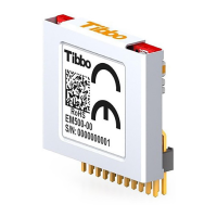
328Tibbo Project System (TPS)
© Tibbo Technology Inc.
Red LEDs are connected to the -CS, SCLK, and MOSI lines. The green LED is
connected to the DONE/MISO line.
Sample project
The use of this Tibbit is illustrated by a Tibbo BASIC test project. Yo can find it
here: https://github.com/tibbotech/CA-Test-Tibbit-26.
Further info
Theory of operation
Resetting and initializing the onboard FPGA
SPI read and write transactions
Registers
Examples of wiring to IR receivers & emitters
Theory of Operation
Before the IR Tibbit can begin normal operation it must be properly reset and
initialized.
Once initialized, the Tibbit is controlled through a number of registers. Registers are
accessed through the SPI interface using SPI read and write transactions.
This Tibbit supports two commands, which are issued through the command
register: receive (record) IR data, and transmit (reproduce) IR data.
The Tibbit looks at IR data as a sequence of "IR light ON" and "IR light OFF" times.
No intelligent data analysis is performed. When recording an incoming IR signal,
Tibbit #26 simply measures ON and OFF times and outputs the data as an array of
measured ON and OFF lengths. Measured lengths represent demodulated IR signal,
i.e. the signal without the carrier frequency. ON and OFF time lengths are expressed
as the number of clock periods of the modulation frequency.
Modulated and unmodulated incoming IR streams
The IR Tibbit can work with IR receivers that output IR data intact, including the
modulation frequency. The Tibbit also works with receivers that filter the carrier
out. Option bit 4 in the command register determines what kind of incoming IR
stream is expected.
If the Tibbit is set to record a modulated incoming IR stream, then it will demodulate
the incoming signal. The modulation frequency will be filtered out, measured (with
averaging), and the corresponding divider value will be stored into the carrier divider
registers. The relationship between the divider value and the modulation frequency
is as follows:
Modulation_frq = 12Mhz / divider_value
If the Tibbit is set to record a demodulated incoming RX stream then it will be
expecting to work with data that doesn't contain the carrier frequency. In this
case, your program must preset the carrier divider registers with the value
corresponding to the expected modulation frequency before starting the recording.
In both cases, ON and OFF period lengths in the information-bearing (demodulated)
signal are measured in periods of the carrier frequency and the resulting data is

 Loading...