248Development Systems
© Tibbo Technology Inc.
- The EM500EV-IB1 board provides a connector for the GA1000 Wi-Fi add-on
module, 1024KBytes of flash memory, and a limited RS232 interface (RX, TX, CTS,
RTS).
Tibbo offers a fully functional serial-over-IP application that can be tested on the
EM500EV. Written in Tibbo BASIC, the application is compatible with Tibbo Device
Server Toolkit software, comes with complete source code, and can be modified by
the user.
EM500EV-MB0
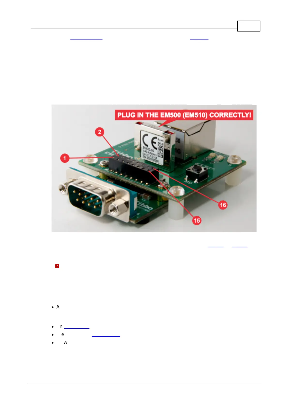
The EM500EV-MB0 board incorporates a socket for inserting the EM500 or EM510
IoT module.
It is physically possible to plug the EM500 (EM510) module into the
EM500EV-MB0 incorrectly. Doing so may irreparably damage the modules.
Only plug the EM500 (EM510) as shown on the photo above.
The EM500EV-MB0 board also features the following:
·
A power jack and a switching regulator with 3.3V output. This 3.3V power is
supplied to the EM500 (EM510) and is also provided on the interface board
connector (see below).
·
An MD button, which is connected to the MD input of the EM500 (EM510).
·
Green and red status LEDs.
·
A two-row interface board connector.
Interface board (IB) connector

 Loading...