Home
Tibbo
Control Unit
EM1000
Tibbo EM1000 User Manual
4
of 1
of 1 rating
570 pages
Give review
Manual
Specs
To Next Page
To Next Page
To Previous Page
To Previous Page
Loading...
32
0
Ti
bbo
P
roj
e
ct
S
ys
t
e
m
(
TP
S)
© Ti
b
b
o Tec
hnol
ogy
Inc
.
Detai
l
s
-
-
-
7
.
2
.
9
.
3
3
#
2
2
,
M
1
S
:
R
T
D
T
e
mp
e
r
a
tur
e
M
e
te
r
F
un
c
ti
on:
R
T
D
t
em
pe
r
a
t
ur
e
m
e
t
er
F
orm
f
a
c
tor:
M1S
C
a
te
gor
y
:
In
pu
t
m
odul
e
Spec
i
al
ne
eds
:
-
-
-
P
ow
e
r
r
e
qui
r
e
m
e
nts:
5V/10
m
A
Mate
s w
i
th:
#1
9
,
#2
0
,
#
21
See
also:
#
29
330
332
Table of Contents
Default Chapter
2
Default Chapter
2
Table of Contents
2
Introduction
12
Legal Information
12
Common Vs. Proprietary Knowledge
15
Embedded Modules
16
EM2000 BASIC/C-Programmable Iot Module
16
Detailed Device Info
19
General-Purpose I/O Lines
23
Wireless Add-On Port, Wi-Fi Communications
24
Ethernet Port Lines
25
Serial Ports
26
Wiegand and Clock/Data Circuit Examples
28
Analog-To-Digital Converter (ADC)
29
I2C/SPI Support (SSI Channels)
29
Square Wave Generator
29
Real-Time Clock (RTC)
30
Flash and EEPROM Memory
30
LED Lines
31
External LCD Support
31
External Keypad Support
32
Power, Reset, PLL Control, and Mode Selection
34
Mechanical Dimensions
35
Ordering Info and Specifications
37
EM1000 BASIC/C-Programmable Ethernet Module
39
EM1000-00 and -01
41
Detailed Device Info
42
General-Purpose I/O Lines
46
Wireless Add-On Port
47
Ethernet Port Lines
48
Serial Ports
51
Square Wave Generator
51
Flash and EEPROM Memory
51
Real-Time Counter
52
LED Lines
53
Power, Reset, PLL Control, and Mode Selection Lines
53
Mechanical Dimensions
55
Ordering Info and Specifications
56
EM1206 BASIC/C-Programmable Ethernet Module
58
Detailed Device Info
61
General-Purpose I/O Lines
63
Ethernet Port Lines
64
Serial Ports
65
Square Wave Generator
65
Flash and EEPROM Memory
65
Real-Time Counter
66
LED Lines
67
Power, Reset, and Mode Selection Lines
67
Onboard Leds
69
Thermal Considerations
69
Mechanical Dimensions
70
Ordering Info and Specifications
71
EM510 "Minimo" BASIC/C-Programmable Iot Module
73
Detailed Device Info
76
Serial Port and General-Purpose I/O Lines
78
Ethernet Port Lines
79
Flash and EEPROM Memory
80
LED Lines
81
Power, Reset, and Mode Selection Lines
82
Mechanical Dimensions
83
Ordering Info and Specifications
83
EM500 "Minimo" BASIC/C-Programmable Ethernet Module
85
Detailed Device Info
87
Serial Port and General-Purpose I/O Lines
89
Ethernet Port Lines
89
Flash and EEPROM Memory
90
LED Lines
91
Power, Reset, and Mode Selection Lines
92
Mechanical Dimensions
94
Ordering Info and Specifications
94
EM1202 BASIC/C-Programmable Ethernet Module
96
Detailed Device Info
98
General-Purpose I/O Lines
100
Ethernet Port Lines
101
Serial Ports
102
Square Wave Generator
102
Flash and EEPROM Memory
102
LED Lines
103
Power, Reset, and Mode Selection Lines
104
Mechanical Dimensions
106
Ordering Info and Specifications
106
Em200
108
Detailed Device Info
110
Ethernet Port Lines
111
Serial Port and General-Purpose I/O Lines
113
Flash and EEPROM Memory
113
LED Lines
113
Power, Reset, and Mode Selection Lines
114
Mechanical Dimensions
115
Ordering Info and Specifications
116
Boards
117
EM2001 BASIC/C-Programmable Iot Board
117
Detailed Device Info
121
General-Purpose I/O Lines
125
Wireless Add-On Port, Wi-Fi Communications
126
Ethernet Port
126
Serial Ports
126
Wiegand and Clock/Data Circuit Examples
128
Analog-To-Digital Converter (ADC)
129
I2C/SPI Support (SSI Channels)
129
Square Wave Generator
129
Flash and EEPROM Memory
130
Leds and LED Lines
130
Real-Time Clock (RTC) and Backup Battery
130
External Keypad Support
131
External LCD Support
131
Power, Reset, PLL Control, and Mode Selection
134
Mechanical Dimensions
135
Ordering Info and Specifications
136
EM1001 BASIC/C-Programmable Iot Board
138
Detailed Device Info
140
General-Purpose I/O Lines
144
Wireless Add-On Port
145
Ethernet Port
145
Serial Ports
146
Square Wave Generator
146
Flash and EEPROM Memory
146
Real-Time Counter and Backup Supercap
147
Leds and LED Lines
147
Power, Reset, PLL Control, MD Button, and Mode Lines
148
Mechanical Dimensions
150
Ordering Info and Specifications
150
Nb10X0 and Ib100X Boards
152
Nb10X0 Network Boards
154
NB1000 Board
154
NB1000 Connectors and Controls
155
Power Jack, Terminals, and Power Regulator
155
Ethernet Jack
156
Jumpers, Buttons and Leds
156
External LED Control
157
Buzzer
158
Ordering Info and Specifications
158
NB1010 Board
159
NB1010 Connectors and Controls
160
Power Jack, Terminals, and Power Regulator
160
Ethernet Jack
161
Jumpers, Buttons and Leds
161
External LED Control
162
Buzzer
164
Optinal GPRS Interface
164
Optional Wi-Fi Interface
164
Ordering Info and Specifications
165
Ib100X Interface Boards
166
Connectors and Headers
167
IB1000, IB1002, and IB1003 (4 Serial Ports)
167
Serial Ports
169
LED Control
171
Ordering Info and Specifications
171
IB1004 and SB1004 (Analog I/O)
172
Terminal Blocks
173
Control Lines
175
Detailed Information
177
A/D Converter
178
D/A Converter
183
Relays
185
RS232/485 Port
186
LED Control
187
IB1005 and SB1005 (Digital I/O)
188
Ordering Info and Specifications
188
Terminal Blocks
189
Control Lines
191
Detailed Information
193
Opto-Isolated Inputs
194
Relays
196
RS232/485 Port
197
LED Control
198
Ordering Info and Specifications
198
Lb100X LED Boards
199
Lb1000 Lb1001
199
Cable Data
201
IC1000 Interboard Cable
201
LC1000 LED Board Cable
202
Mechanical Data
203
Nb10X0 and Ib100X Board Dimensions
203
Sb100X Board Dimensions
205
Lb100X Board Dimensions
207
Ds1206N
209
DS1206N Hardware
212
Power Arrangement
212
Ethernet Port
213
Multi-Channel Serial Port
214
Flash and EEPROM Memory
216
Mechanical Dimensions
217
Ordering Info and Specifications
218
Em1202Ev
220
EM1202EV Hardware
222
Power Arrangement
223
Ethernet Port
223
Multi-Channel Serial Port
224
Additional Information on Serial Port Lines
226
Flash and EEPROM Memory
227
Mechanical Dimensions
228
Ordering Info and Specifications
229
Em1206Ev
231
Wireless Add-On Connector
232
Main and Backup Power
233
Multi-Channel RS232 Port and Expansion Connector
234
Em120/Em200-Ev
237
Power Jack
237
Ethernet Port Pin Assignment
238
RS232 Port Pin Assignment
238
Expansion Connector Pin Assignment
239
Development Systems
240
Em2000Ev
240
Em1000Ev
242
Em1000Tev
243
Tev-Mb0
244
Tev-Kb0
244
TEV-Lbx Boards
246
Tev-Lb0
248
Tev-Lb1
250
Tev-Lb2
251
TEV-Ibx Boards
253
Tev-Ib0
254
Tev-Ib1
255
Ordering Info
257
Em500Ev/Em510Ev
258
Em500Ev-Mb0
259
Em500Ev-Ib0
260
Em500Ev-Ib1
261
Em500Ev-Ib2
262
Ordering Info
263
Tibbo Project System (TPS)
265
TPS: the General View
266
Tibbits
267
Tibbit Form Factors & Colors
267
M1 "Narrow" Tibbits
268
M2 "Wide" Tibbits
270
C1 "Narrow" Tibbits
272
C2 "Wide" Tibbits
273
H1 "Hybrid" Tibbits
275
H2 "Hybrid" Tibbits
276
Tibbit Power Lines
277
Tibbit Sockets and Tiles
278
Electrical Connections on a Tile
280
Tibbits with "Special Needs
282
[SER] Tibbits that Require UART Functionality
282
[INT] Tibbits that Require an Interrupt Line
283
[CAN] Tibbits that Require CAN Functionality
284
[POE] Tibbits that Require Poe Power Lines
284
[AUD] Tibbits that Require Audio Functionality
285
[MMC] Tibbits that Require MMC (SD) Functionality
285
[USB] Tibbits that Require USB Functionality
285
Combining "C" and "M" Tibbits
285
C1 + M1
286
C2 + M2
287
C2 + Two M1S
288
Two C1S + M2
289
Tibbit Leds and Their Colors
289
Labeling
291
Available Tibbits
291
M1S: Four Direct I/O Lines
293
M1S: Three Direct I/O Lines and Ground
294
M1S: Two Direct I/O Lines, +5V Power, Ground
295
01, M1S: Four-Line RS232 Port
297
02, M2S: RS232/422/485 Port
298
M1S: Two Low-Power Relays (Configuration 1)
301
M1S: Two Low-Power Relays (Configuration 2)
302
M1S: Two Isolated Inputs
303
M1S: Three Isolated Inputs, Common (-)
304
M1S: Three Isolated Inputs, Common (+)
305
M1S: Four Opto-Inputs, Common Ground
306
M1S: Two 24V Isolated Inputs
307
M1S: Three 24V Isolated Inputs, Common (-)
308
M1S: Three 24V Isolated Inputs, Common (+)
309
M1S: Four 24V Isolated Inputs, Common Ground
310
05, M1S: RS485 Port
311
06, M2T: Two High-Power Relays
312
07, M1S: Two Solid State Relays
314
08, M1S: Wiegand and Clock/Data Reader Port
315
09, M1S: Low-Power 5V Supply, 12V Input
316
10, M1T: Medium-Power 5V Supply, 12 V Input
317
11, M1S: Four Open Collector Outputs
318
12, M1S: Low-Power +15/-15V Power Supply, 5V Input
320
13, M1S: Four-Channel ADC
321
14, M1S: Four-Channel DAC
322
15, H1: High-Voltage AC Solid State Relay
323
16, M1S: Three Pwms with OC Outputs
325
17, M1S: Three Pwms with Power Outputs
326
18, C1: Power Input
328
19, C2: DB9M Connector
329
20, C2: Nine Terminal Blocks
329
21, C1: Four Terminal Blocks
330
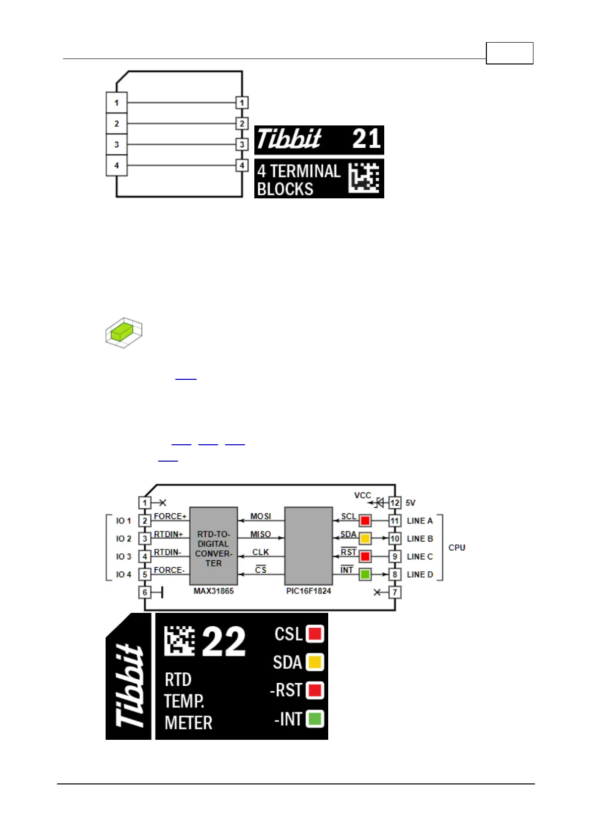
22, M1S: RTD Temperature Meter
331
23, M2T: Isolated Poe Power Supply, 5V Output
333
25: M2S: High-Power 5V Supply, 12/24/48V Input
335
26, M1S: IR Command Processor
337
Theory of Operation
339
Resetting and Initializing the Onboard FPGA
340
SPI Read and Write Transactions
341
Registers
342
Command Register
343
Status Register
343
TX Length Registers
343
Carrier Divider Registers
344
RX Length Registers
344
TX and RX Data Buffers
344
Examples of Wiring to IR Receivers & Emitters
345
27, C1: IR Receiver/Transmitter
346
28, C1: Ambient Light Sensor
347
29, C1: Ambient Temperature Meter
347
30, C1: Ambient Humidity/Temperature Meter
348
31, C1: PIC Coprocessor
349
35, C1: Barometric Pressure Sensor
351
36, C1: 3-Axis Accelerometer
352
37, C1: RF Connector
353
38: C1: Pushbutton
354
4, C1: Large LED (Four Colors Available)
355
4, M1S: Digital Potentiometer (Four Nominals)
356
41, C1: 8-Bit Port
357
42, M1S: RTC and NVRAM with Backup
358
H2: Isolated RS232/422/485 Port (DB9M Connector)
360
H2: Isolated RS232/422/485 Port (Terminal Block)
363
3, H2: LTE (4G) Modem
366
47, H2: GPRS Modem [DEPRECATED]
371
48, H2: Audio In/Out [DEPRECATED]
374
49, C2: Micro SD Card Slot [DEPRECATED]
376
50, C1: Mini Type B USB Port [DEPRECATED]
377
51, M1S: CAN Bus [DEPRICATED]
378
52, M2S: Four-Channel Isolated +/-10V ADC
379
53, M2S: Isolated 4-20Ma ADC
381
54, M1S: Four Dry Contact Inputs
383
56, C1: Type a USB Port [DEPRECATED]
384
57, M1S: FPGA Tibbit
385
Resetting and Initializing the Onboard FPGA
386
Implemented Configurations
387
Smart LED Controller Configuration
387
58, M1S: Two 24V NPN Isolated Open Collector Outputs
389
59, M1S: Two 24V PNP Isolated Open Collector Outputs
391
Tibbo Project Pcbs (Tpps)
392
Available TPP Models
393
Size 2 Tibbo Project PCB (TPP2), Gen 2
393
Tiles, Sockets, Connectors, Controls
397
Size 3 Tibbo Project PCB (TPP3), Gen 2
398
Tiles, Sockets, Connectors, Controls
401
Size 2 Tibbo Project PCB (TPP2)
402
Tiles, Sockets, Connectors, Controls
405
Size 3 Tibbo Project PCB (TPP3)
406
Tiles, Sockets, Connectors, Controls
408
Size 3 Linux Tibbo Project PCB (LTPP3)
409
Tiles, Sockets, Connectors, Controls
411
Network Configuration
412
Firmware Updates
413
Size 3 Linux Tibbo Project PCB (LTPP3), Gen 2
416
Tiles, Sockets, Connectors, Controls
418
Plus1 (SP7021) CPU
419
Common Information
421
Firmware Updates
421
Ethernet Port
422
MD and RST Buttons
422
Power Arrangement
422
Leds
423
Buzzer
425
Keypad Connector (TPP2 Only)
425
LCD Display Connector (TPP2 Only)
425
Optional Wi-Fi Interface
426
Tibbo Project Box (TPB) Kits
427
TPB Structure
428
Available Tibbo Project Box Kits
429
Size 2 Tibbo Project Box (TPB2)
429
TPB2 Parts and Accessories
430
Size 2 Vibration Protection Kit (VPK)
431
Mechanical Dimensions
432
Size 2 Project Box with Lcd/Keys (TPB2L)
432
TPB2L Parts and Accessories
433
Size 2 Vibration Protection Kit (VPK)
434
Mechanical Dimensions
435
Size 3 Tibbo Project Box (TPB3)
436
TPB3 Parts and Accessories
437
Size 3 Vibration Protection Kit (VPK)
438
Mechanical Dimensions
439
Size 3 Linux Tibbo Project Box (LTPB3)
439
LTPB3 Parts and Accessories
440
Size 3 Vibration Protection Kit (VPK) for LTPB3
441
Mechanical Dimensions
442
Retail Packaging
443
TPB2/TPS2 Retail Packaging Kit
444
TPB2L/TPS2L Retail Packaging Kit
445
TPB3/TPS3 Retail Packaging Kit
446
Assembled Retail Package
447
Linux on TPS
448
Serial Console
448
Web Interface
449
Secure Shell (SSH)
453
CLI Utilities
454
External Controllers
455
Ds110X
456
Ds110X Connectors and Controls
459
Power Arrangement
459
Ds1100 Ds1101 Ds1102
460
Ds1100 Ds1101 Ds1102
462
Ethernet Port
462
Serial Port
462
Mapping Options for the RS232 Mode
466
Flash and EEPROM Memory
467
Mapping Options for the RS422 Mode
467
Mapping Options for the RS485 Mode
467
Buzzer (DS1101 and DS1102)
468
Optional Wi-Fi (DS1101 and DS1102)
468
Optional OLED Display (DS1101 and DS1102)
469
LED Bar (DS1101 and DS1102)
470
DIN Rail and Wall Mounting Plates
471
Ordering Info and Specifications
472
Ds1206
475
DS1206 Connectors and Controls
477
Power Arrangement
477
Ethernet Port
478
Multi-Channel RS232 Port
479
Flash and EEPROM Memory
480
Ordering Info and Specifications
481
Ds1202
482
DS1202 Connectors and Controls
484
Power Arrangement
485
Ethernet Port
485
Multi-Channel RS232 Port
485
Flash and EEPROM Memory
487
Ordering Info and Specifications
488
Ds10Xx
489
Common Features of the Ds10Xx Family
490
Secondary Cover
490
DIN Rail Mounting
492
Ds10X0, Ds10X2, Ds10X3 (4 Serial Ports)
492
Ordering Info and Specifications
493
Ds10X4 (Analog I/O)
495
Ordering Info and Specifications
496
Ds10X5 (Digital I/O)
497
Ordering Info and Specifications
498
Sensors (Probes)
499
RS485 Modbus Sensors ("Bus Probes")
499
Connectors and Controls
500
Modbus Registers of Bus Probes
501
Setting up and Testing Bus Probes
505
Setting Modbus Ids
505
Updating Probe Firmware
506
Status Leds
508
Outline Dimensions
510
Ordering Info and Specifications
510
Cable Probes
512
Wire Connections
513
Testing Cable Probes
514
Outline Dimensions
514
Ordering and Specifications
515
Companion Products
516
Wa2000
516
Connector Pin Assignment
518
Connecting WA2000 to Tibbo Devices
519
Status LED
520
Firmware Upgrades
520
Mechanical Dimensions
521
Ordering Info and Specifications
522
Ga1000
523
Connector Pin Assignment
524
Connecting GA1000 to Tibbo Devices
525
Status LED
527
Mechanical DIM Ensions
528
Ordering Info and Specifications
529
RJ203 Jack/Magnetics Module
530
Interface Pads
530
Interfacing the RJ203 to the DM9000B
531
Using the RJ203 with the EM203 and Other Modules
532
Mechanical Dimensions: RJ203
533
Mechanical Dimensions: RJ203+EM203
534
Mechanical Dimensions: RJ203+EM1206
535
Ordering Info and Specifications
536
Accessories
537
WAS-P0004(B) DS-To-Device Serial Cable
537
WAS-P0005(B) DS-To-PC Serial Cable
537
WAS-1499 'Straight' Ethernet Cable
538
WAS-1498 'Crossover' Ethernet Cable
538
12VDC Power Adaptors
538
TB100 Terminal Block Adaptor
539
TB1000 Terminal Block Adaptor
540
TB1004 Test Board
541
TB1005 Test Board
543
Setup (MD) Button (Line)
544
Status Leds (LED Control Lines)
545
Monitor/Loader (M/L)
546
Update Modes
547
Update Mode Selection Flowchart
548
Xmodem Serial Updates
551
TPS Devices
553
Programmable Serial Controllers
554
Programmable Boards and Modules
554
4
Based on 1 rating
Ask a question
Give review
Questions and Answers:
Need help?
Do you have a question about the Tibbo EM1000 and is the answer not in the manual?
Ask a question
Tibbo EM1000 Specifications
General
Brand
Tibbo
Model
EM1000
Category
Control Unit
Language
English