160Boards
© Tibbo Technology Inc.
*IB1002 and IB1003 boards only
Serial port 4
*IB1002 and IB1003 boards only
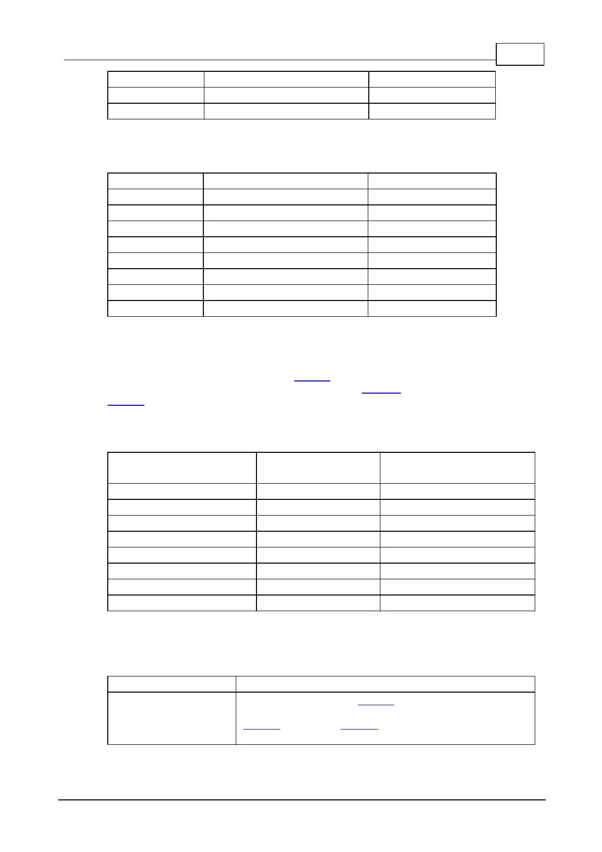
LED Control
The IB1000 works with the standard LB1001 LED board and controls the LEDs
through 8 general-purpose I/O (GPIO) lines of the EM1000 module (installed on the
NB10x0 network board). To turn the LED on, set the corresponding line LOW. Do not
forget to configure LED control lines as outputs. This is done through the io.enabled
property of the .io object (see TIDE, TiOS, Tibbo BASIC, and Tibbo C Manual).
Ordering Info and Specifications
The IB1000 board and LB1001 LED board mounted on
the IB1000 and connected to the latter with the
LC1000 cable. The TB1000 terminal block adaptor is not
included with this product.
 Loading...