172Boards
© Tibbo Technology Inc.
Clock speed limitations
The A/D converter is optically isolated from the rest of the device, so there are
opto-couplers on all interface lines. Opto-couplers are relatively slow devices. This
imposes a limit on how fast the clock line can be toggled. The minimum clock period
is 200us. Both half-periods must be at least 100uS long. This means, that the
conversion result can be obtained in 200uS*24=4.8ms or 200uS*16=3.2ms.
D/A Converter
The D/A converter is based on the Analog Devices' 14-bit AD7836 chip and has 4
independent output channels with 14-bit resulution. Each of the four channels have
independent voltage and current output lines (both can be used at the same time if
needed).
Each channel has two outputs: one voltage and one current output. The voltage
outputs have +/-10V range (20mA max load). Writing all 1's (14 of them) into the
D/A channel produces the maximum positive level on the voltage output (+10V
nominal), writing all 0's produces the maximum negative level on the voltage output
(-10V nominal). Writing a "middle" binary value of "10000000000000" (that's 1
followed by 13 zeroes) produces a 0V output. Of course, this explanation is idealized
as it doesn't take into account inevitable conversion errors.
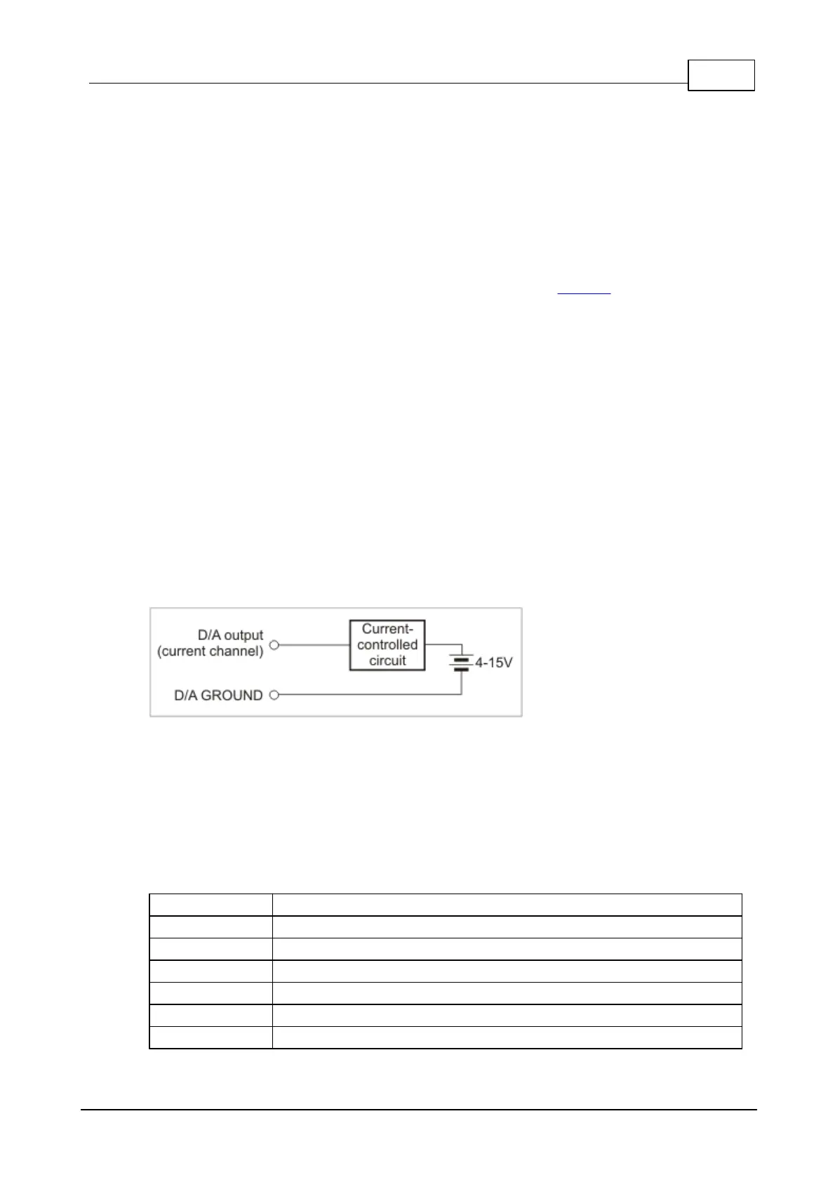
The output current range on the current output is 0-20mA. An external 4-15V
power source is required for current outputs to work. Writing all 1's into the D/A
channel results the maximum output current. Writing a middle value
(10000000000000B) results in zero current. Writing any value below that still
produces zero current. Hence, the actual resolution of the current output is not 14,
but 13 bits.
The D/A converter has full galvanic isolation from the rest of the IB1004 + SB1004
circuitry: the power for the D/A section is generated by an isolated switching power
supply, all control lines use opto-couplers.
D/A outputs
All D/A-related lines are available on a 9-pin terminal block #3:
D/A channel 4, current output
D/A channel 4, voltage output
D/A channel 3, current output
D/A channel 3, voltage output
D/A channel 2, current output
D/A channel 2, voltage output
 Loading...