173 Programmable Hardware Manual (PHM)
© Tibbo Technology Inc.
D/A channel 1, current output
D/A channel 1, voltage output
D/A GROUND (isolated from the rest of the device)
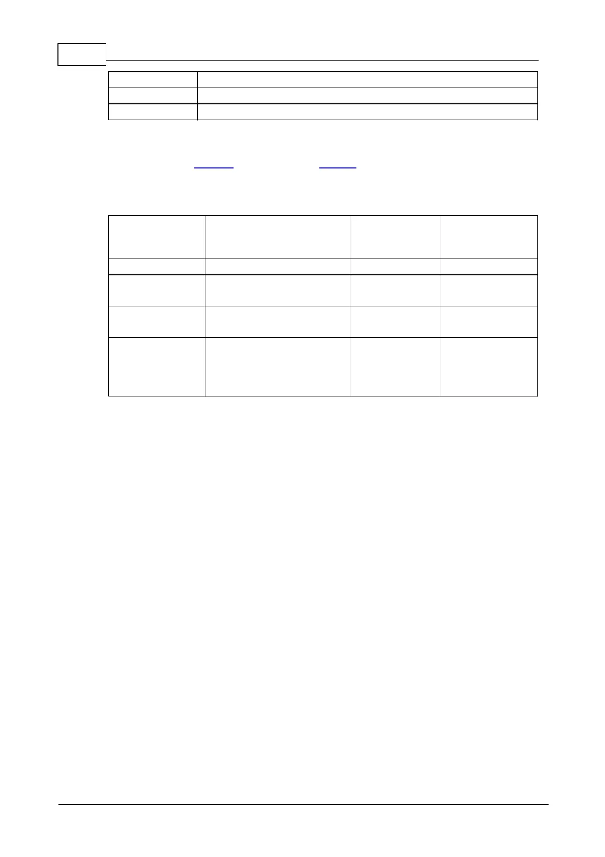
D/A control
Four lines of the EM1000 (located on the NB10x0 network board) control the D/A
converter. In the table below, "output" means an output of the EM1000, and "input"
means an input of the EM1000:
Serial clock
(LOW idle state)
Data latch strobe
(active LOW)
Output enable:
HIGH (or input*) -
disabled
LOW - enabled
*GPIO line configured as input (default state)
The D/A converter control cycle consists of the following steps. First, a 16-bit data
word is serially clocked into the D/A circuit. Bits 15 and 14 of the data word select
the output channel, remaining 14 bits carry desired output value. The word is sent
most significant bit first.
Two lines -- CLOCK and DATA -- are used for sending the data word to the D/A
converter. Inactive state for the CLOCK line is LOW. Each write transaction consists
of 16 clock pulses. With each LOW-to-HIGH transition on the CLOCK line, the state
of the DATA line is latched into the D/A converter. The process is illustrated below.
Once all 16 bits have been clocked in, the negative pulse on the WR line sets new
data and the new analog value appears on the outputs of the corresponding D/A
channel (provided that the EN lines is at low).

 Loading...