152Boards
© Tibbo Technology Inc.
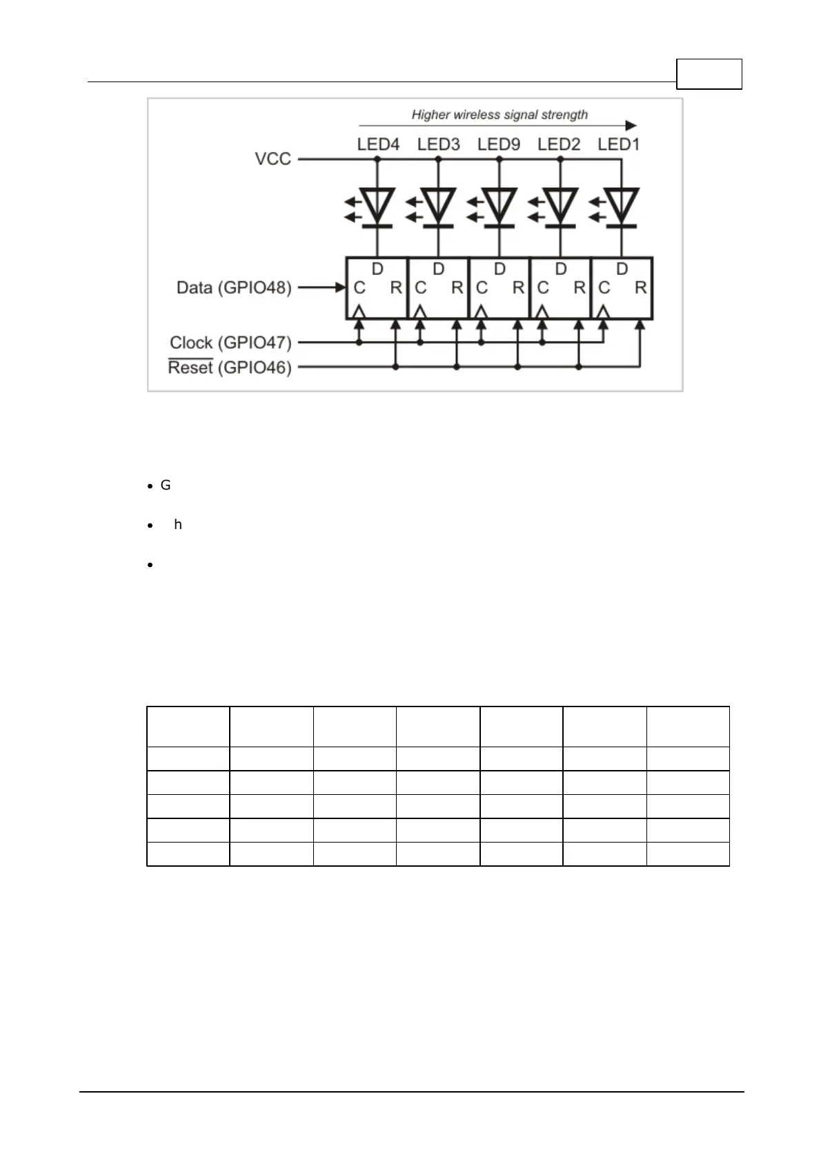
If you want to switch an LED ON then set the data line LOW. The data bit for the
LED#1 (indicating the highest signal strength) is clocked in first. That's the short
explanation. In further detail, we can say:
·
GPIO 48 is the Data line; set it to the state that you wish the LED to be in, LOW
= ON, HIGH = OFF.
·
When you then pull GPIO 47 (Clock line) from its normal state (HIGH) to LOW and
then back to HIGH, the state of the Data line is read in and used for LED1.
·
If you want to turn on LED2 (for example) you have to set GPIO 48 to LOW,
toggle the clock once (HIGH-LOW-HIGH) which would set LED1 ON, set GPIO48 to
HIGH (because you want LED1 off) and then just toggle the clock again (HIGH-
LOW-HIGH). At this point, the state of LED1 would shift to LED2 (so LED2 would
light up).
So assuming that all LEDs are OFF and each row means that we have toggled
through one clock cycle:
As you can see, each clock cycle sets a new state for LED1 which directly
corresponds to the state of the Data line, and shifts all previous LED states.
 Loading...