260Tibbo Project System (TPS)
© Tibbo Technology Inc.
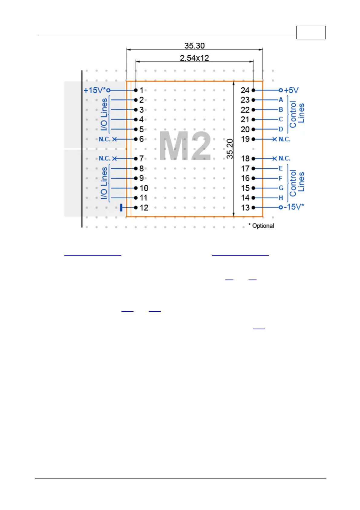
Pins 14-17 and 20-23 are control lines A-H. They are for interfacing to our
embedded modules or other microcontrollers. On Tibbo Project PCBs these pins are
connected to the main CPU.
Pins 2-5 and 8-11 are I/O lines facing the outside world. On Tibbo Project PCBs
they go to Tibbit connector sockets (i.e. connect to C1 and C2 devices).
Pins 12 and 24 are the GROUND and +5V power pins. Most Tibbit Modules consume
(take) 5V power. There are also power supply Tibbits that generate 5V power from
a variety of sources. Those output 5V through pin 12. As an example of power
Tibbits see Tibbits #10 and #23.
Pins 1 and 13 are for the additional +15V and -15V voltages. These are optional
and only needed by few Tibbits. A special power supply Tibbit #12 generates +/-
15V from the main 5V power.
Pins 6, 7, 18 and 19 are unused and should be left unconnected.
Notice that each pin row has a "missing pin" in this middle. This separates a row into
two groups of 6 pins.

 Loading...