316Tibbo Project System (TPS)
© Tibbo Technology Inc.
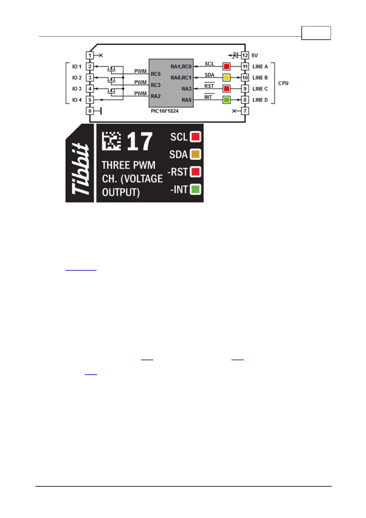
Details
This Tibbit is based on the PIC16F1824 microcontroller and takes advantage of the
PWM channels available on this PIC device. The PIC micro has four PWM channels
but one of the channels cannot be used because it shares I/O lines with the I2C
interface. The I2C interface is utilized for communications with the main CPU of the
TPP board and also for PIC firmware upgrades.
The frequency and the pulse width (duty cycle) are set independently for each
PWM channel. The frequency is controlled through a divider and a period value. The
divider allows you to select the base frequency applied to the divider. Available
choices are 32MHz, 8MHz, 2MHz, and 500KHz. The output signal of the PWM can
then be programmed to have the period equal to 4~1024 base frequency periods in
4-period steps (i.e. 4, 8, 12,...1020, 1024). This gives you the output range from
8MHz down to 488Hz. The PWM pulse width can be programmed to have the period
equal to 1~1024 base frequency periods in 1-period steps (1, 2, 3,... 1023, 1024).
Each PWM channel uses one Singreat Electronics GT430PSB P-channel FET
transistor which is rated for 4A continuous current at room temperature.
Combine this Tibbit with #20 (nine terminal blocks) or #19 (DB9M connector). It's
not common but possible to use the latter for wiring into the PWM outputs. The
Tibbit #21 (four terminal blocks) can also be used but you will have to steal the
ground elsewhere, as #21 doesn't have its own ground line and the PWM Tibbit
outputs voltages with respect to the system ground.
LEDs
There are two red, one yellow, and one green LED. The first red LED is connected to
the SCL line of the I2C interface, the second one -- to the -RST line of the PIC
micro. The yellow LED is connected to the SDA line of the I2C interface. The green
LED is on the -INT line.
PIC micro and GRA firmware

 Loading...