43 Programmable Hardware Manual (PHM)
© Tibbo Technology Inc.
Please, do not forget that the VCCB pin should not be left unconnected (see Real-
time Counter).
Proper external reset is not required. The EM1000 has a reliable power-on reset
circuit with brown-out detection. Optionally, you can connect a reset button or
some other reset-generating circuit to the RST pin of the EM1000. This will allow
you to generate "external" resets. The RST line has active HIGH polarity. If you are
not using the RST pin you can leave it unconnected.
The main clock frequency of the EM1000 is generated by the 11.0592MHz crystal
connected to the onboard PLL circuit. When the PLL is off, the EM1000 is clocked at
11.0592MHz. When the PLL is on, the main clock is eight times higher- 88.4736MHz.
Naturally, with PLL turned on the EM1000 works 8 times faster and consumers more
current (230mA with PLL on against 110mA with PLL off). Main clock frequency also
affects the baudrates of serial ports when in the UART mode, as well as the
frequency produced by the square wave generator.
The PLL cannot be switched off and on while the EM1000 is running. This is because
when the PLL mode changes its output needs some time to stabilize. For this
reason, the PLL mode of the EM1000 can only be changed on reset. A special
internal delay circuit will hold the EM1000 in reset while PLL frequency stabilizes.
The state of the PM pin at power-on or external reset (i.e. reset pulse on the RST
line) defines whether the EM1000 will run with PLL on or off. To have the PLL on,
leave the PM pin unconnected. To disable PLL and run at lower clock frequency,
ground the PM pin.
Your Tibbo BASIC/C application can also change the PLL mode programmatically.
The Tibbo BASIC/C application can check the current PLL mode through the system
(sys.) object (see TIDE, TiOS, Tibbo BASIC, and Tibbo C Manual). If the PLL mode
needs to be changed, the application can set new mode and then perform an
internal reset (again, through the system object). The internal reset is identical to
the power-on or external reset with one difference: the PLL mode is set basing not
on the PM pin but on the PLL mode requested by the application prior to the reset.
The function of the MD line is described in Setup Button (MD line).
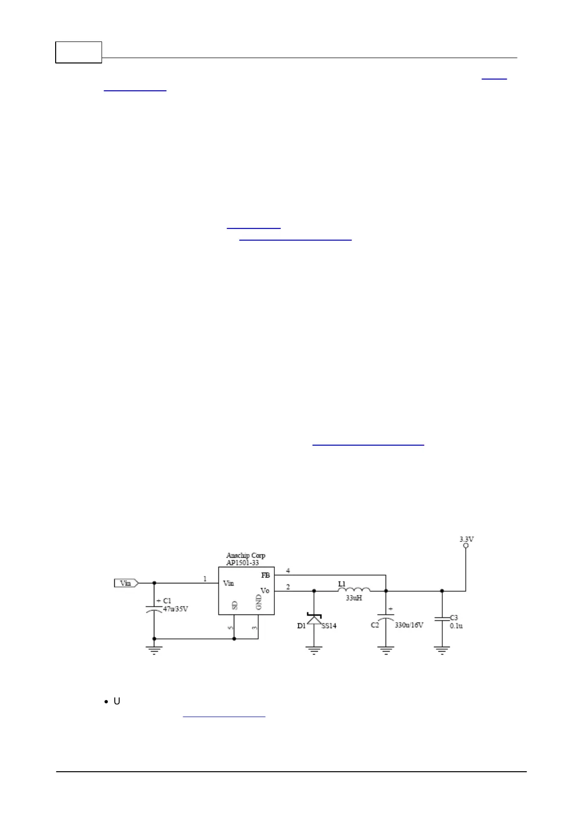
Power supply circuit
Many power supply circuits will work well. The one below is being used by Tibbo.
The circuit can handle input voltages in the 9-24V range.
Notes:
·
U1 (AP1501-33) is a popular power IC manufactured by Anachip (now Diodes
Incorporated, www.diodes.com)

 Loading...