531 Programmable Hardware Manual (PHM)
© Tibbo Technology Inc.
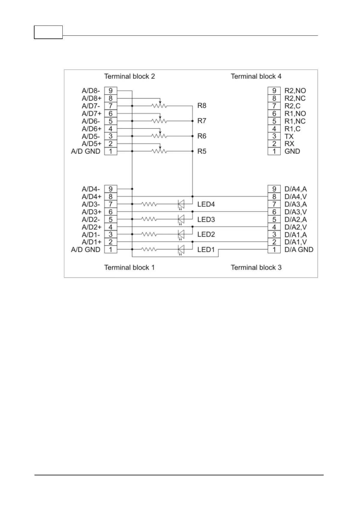
outputs into A/D inputs of the DS1004. Schematic diagram of the test board's
connections is shown below:
Voltage outputs of D/A channels 1-4 are connected directly to A/D inputs 1-4, and
also to four red LEDs 1-4. The brightness of these LEDs is proportional to the
voltage on D/A outputs. Obviously, LEDs will only work for positive output voltages
and will stay off for negative voltages. Thus, LEDs provide indication only for 1/2 of
the D/As' output range.
Current outputs of D/A channels are not used at all and can't be tested with the
TB1004 board.
A/D inputs 4-8 are wired into the circuit through four adjustable resistors R1-4.
Voltage for these resistors comes from the D/A output 4. Therefore, the voltages on
central taps of R1-4 are a fraction of the current output of D/A 4.
 Loading...