66Embedded Modules
© Tibbo Technology Inc.
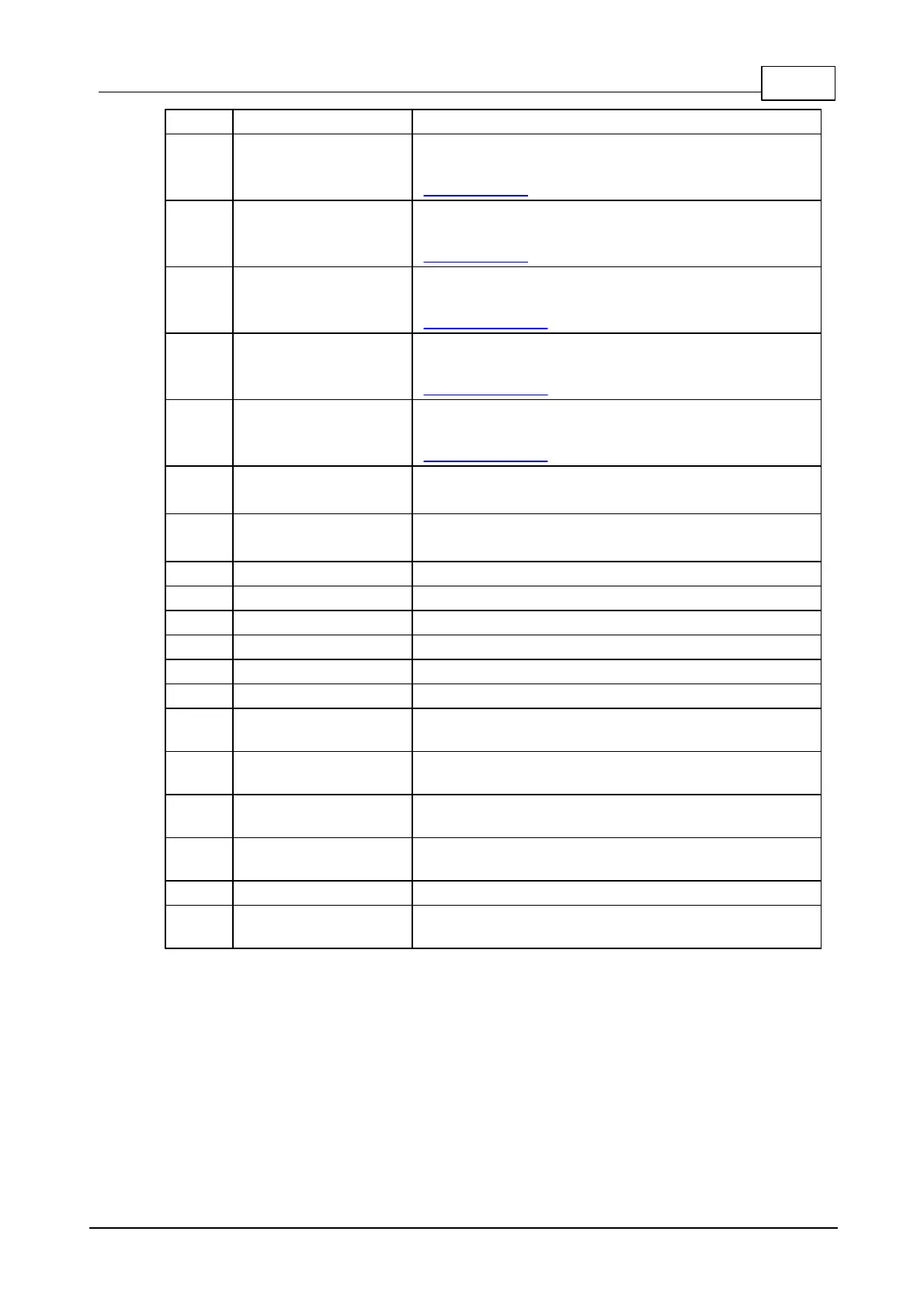
General-purpose I/O line 2 (P0.2).
General-purpose I/O line 3 (P0.3);
This pin is also used for interfacing to the
external flash.
General-purpose I/O line 4 (P0.4);
This pin is also used for interfacing to the
external flash.
General-purpose I/O line 5 (P0.5);
This pin is also used for interfacing to the
WA2000 add-on.
General-purpose I/O line 6 (P0.6);
This pin is also used for interfacing to the
WA2000 add-on.
General-purpose I/O line 7 (P0.7);
This pin is also used for interfacing to the
WA2000 add-on.
General-purpose I/O line 8 (P1.0);
RX, W1, and din input of the serial port.
General-purpose I/O line 9 (P1.1);
TX, W1, and dout output of the serial port.
Reset input, active low. External reset is optional.
Link status LED control line.
Dual-function red status LED control line.
Dual-function green status LED control line.
Ethernet port, negative line of the differential
input signal pair.
Ethernet port, positive line of the differential
input signal pair.
Ethernet port, negative line of the differential
output signal pair.
Ethernet port, positive line of the differential
output signal pair.
"Clean" power output for magnetics circuitry.
Positive power input, 3.3V nominal, +/- 5%, max.
current consumption 110mA.
Notes:
1. This line can serve as an RTS/Wout/cout line of a serial port.
2. This line can serve as a CTS/W0&1in/cin line of a serial port.
 Loading...